G4 Re-assembly Questions

Discuss the coveted printers saw

Moderator: crzypete

Post Reply
Daninvan
Posts: 50
Joined: Mon Oct 05, 2009 8:55 pm
Location: Vancouver BC

G4 Re-assembly Questions

Post by Daninvan »

I am in the process of re-assembling my Glider after a total teardown, media blasting, and powdercoating.

I have some questions about the reassembly that I hope this group might be able to help me with.

The black knob AKA handwheel used for turning the micrometer gauge is supposed to have a "TX-1174 lock screw" to secure it to the shaft. What does this lock screw look like and how does it attach?


Image[/img]

Next, on the clamp there is supposed to be a washer TX-158. I am not sure that my clamp had one of these, does anyone have a picture they could show me?

Image[/img]

Finally (for now!), the arbor. I have a piece that looks like it belongs on the arbor, but is not shown on any drawings or teardown pictures I have seen. Anyone know what this piece is?? This is the piece with the red arrow pointing to it.

And the other finally is the blue arrows. They are pointing to what appear to be me to be thin clips or washers. This is picture of a G4B teardown from the internet. I don't seem to have these clips. Any ideas on if I am missing them, or did the G4 not have them?

Image[/img]

Thanks in advance for your help!

Dan
crzypete
Posts: 1691
Joined: Thu Dec 16, 2004 10:45 am
Location: New York State
Contact:

Post by crzypete »

Da,n,

I think I can help with a number of these questions.

1 the locknut for the plastic adjustment wheel should be inside of it- basically it is a set screw which you tighten against the end of the leadscrew, it will be 1/2- 20" threads.

2. not sure about the clamp washer

3.I believe the odd bronze thing is an add on that someone made to take the place of the grinding wheel. If my theory is correct it would fit between the outermost flange on the right and the pulley.

4 those clips are bearing specific in that photo- they held the seals of those bearings in- you can see that the bearing on the right still has one on, but the bearing on the left is missing it. This is nothing you need.

Pete
Daninvan
Posts: 50
Joined: Mon Oct 05, 2009 8:55 pm
Location: Vancouver BC

Post by Daninvan »

Pete,

Thanks for the tips. I think you are right on all counts!

Upon further examination I think the odd bronze thing actually went in between the pulley and the outer arbor bearing. My (few) disassembly photos show the pulley away from the arbor, and it has the correct ID for that. Seems odd they would do that, which would also entail having to move the motor to match.

Dan
Daninvan
Posts: 50
Joined: Mon Oct 05, 2009 8:55 pm
Location: Vancouver BC

Post by Daninvan »

Next set of questions:

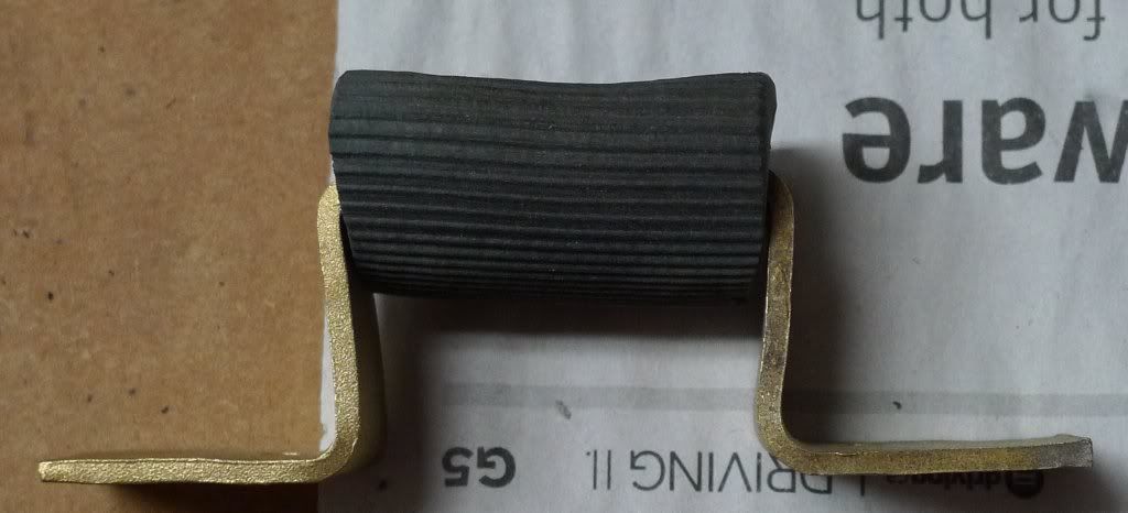
1. Underneath the hinged part of the table that rises up as the blade rises up there is a stop. The stop on my machine (pictured) looks different than the stop in the manual, I'm guessing mine is non original. Wondering what the original one looked like - just a strip of rubber?
Image

2. Looking ahead to the ball bearings for the sliding table. Is there a trick to reinstalling them? It looks at the very least like a helper will be required! Also, what do you recommend for lubricating them and the ways?

Thanks,

Dan
crzypete
Posts: 1691
Joined: Thu Dec 16, 2004 10:45 am
Location: New York State
Contact:

Post by crzypete »

That is definitely not the original stop. As I recall, it was just a coupe of shims on top of the bearing block- I'd check, but have no G4's around at the moment.

I run my ways dry as they spec. You can add some graphite powder to give it some lube, but in general oil and wax just gum up. I end up cleaning my ways when they start running poorly- this is specced on the hammond plate on my saw.

re-installing is actually pretty easy, you just start inserting the balls as you go. There are probably two felt washers that would go on the outside of the middle two balls. Once you have the balls all in and the stop back in place you will need to align it all. This is done by bumping the table at the ends of its travel. This should actually be done fairly routinely, whenever the table starts shortening the length that it is sliding.

Pete
Daninvan
Posts: 50
Joined: Mon Oct 05, 2009 8:55 pm
Location: Vancouver BC

Post by Daninvan »

Felt washers on the ball bearings? I definitely did not have those on my machine. What is their purpose and what do they look like?

Reading the article by Bob Vaughan, he stresses the importance of keeping the same number of washers in their original 3 locations when you reassemble the table onto the stand. But the arbor is mounted on a hinge that is attached to the table itself, not the stand. So these washers do not affect the relationship between the table and the blade at all. Why then are these washers so critical?

The blade that came with my saw is a 6" blade. If I understand correctly, these saws will take up to 7 1/4" without modification?

(Making good progress on the assembly, just going slow and trying to get it all right. There is a fair bit of touching up to do, and running to the hardware store, etc)
crzypete
Posts: 1691
Joined: Thu Dec 16, 2004 10:45 am
Location: New York State
Contact:

Post by crzypete »

Dan, i have to ask and confirm that you have a G4 not a G100.

Bob Vaughn's redo is of a G100 which is constructed differently than a G4, the G100 has a removable section of table in the front right corner- The G4 has the same section, but it is cast in place. It is very helpful that you keep the factory shims on the G100 so that you do not have to figure it out yourself. The G4 has no such issues.

The G100 needs no modification for a 7 1/4" blade. The G4 needs slight modification. The modification is so slight you will not be able to tell it has been changed with the saw in everyday use.

If you put a 7 1/4" blade on the saw and try to crank it up and down- you will see one moment in its travel that it wants to hit the table.To modify the G4 for a 7 1/4" blade you need to undercut the throat just a bit- like 1/4" total at the deepest part. You can taper this cut so it does not show on the visible top.

The felt washers may be more of a hard fiber(may be metal too, its been a while since I was in there.) They were only on the G4's as well. They seem to space the carriage off of the side walls and perhaps keep it from vibrating in an acoustical way. I would not be surprised if they were missing and not be too worried about running it without them. The look like a washer whose center hole is approximately the size of one of the ball bearings. Of course, if you have a g100 with its fully contained ball bearing slides, it is totally different and you should ignore this.

Pete
Daninvan
Posts: 50
Joined: Mon Oct 05, 2009 8:55 pm
Location: Vancouver BC

Post by Daninvan »

Pete,

Thanks again for all your help with this!!

My Hammond is indeed a G4.

I was supposed to be away today, but wound up having to cancel the trip and stick close to home. So I actually made some good progress on the rebuild.

I finally got the ball bearings in, my problem with them turned out to be that there was paint on the edge of the sliding table and on the edge of the fixed table it slides past. Just that small amount of paint was causing it to bind.

Image

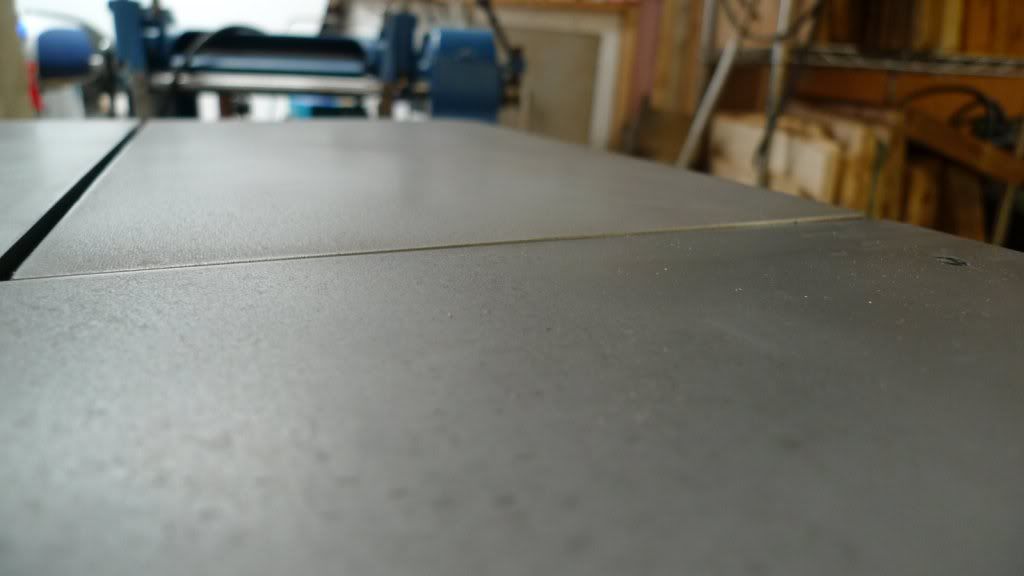
The problem du jour is that the hinged portion of the table that lifts up with the motor does not sit even with the fixed portion of the table, when it is in the 'down' position. You can see on this picture that the hinged table is flush on the left but slightly proud on the right. Before I started doing too much fooling around I thought I'd see what you might suggest would be the best place to start correcting this.

Image

Dan
crzypete
Posts: 1691
Joined: Thu Dec 16, 2004 10:45 am
Location: New York State
Contact:

Post by crzypete »

hey Dan, the progress is looking good. It is a good thing for you that Hammond thought of just about everything. The back of that table is actually cammed, You can adjust the rod that it pivots on to take it through a full range of motion, you should find a position in which it lines up very nicely.

Pete
Daninvan
Posts: 50
Joined: Mon Oct 05, 2009 8:55 pm
Location: Vancouver BC

Post by Daninvan »

You are right, they did think of everything! Sometimes it is so complicated I think "what the heck??"!

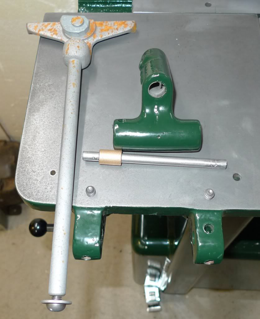
For the part below, the hinged doodad that holds the batter gauge, I've laid out in the picture all the parts I have for it, but I am sure I am missing something still. Why does the long pivot pin go thru that brass piece? Is there supposed to be a spring or something? And why is the hole in the right side support significantly larger in diameter than the pivot pin? And why does the right side support have holes for three set screws? (rust is from an unfortunately located leak in the garage roof)

Image

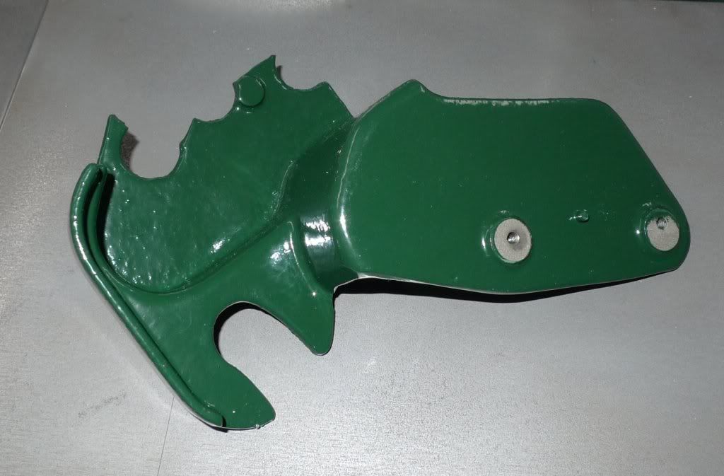
This part was on top of my saw when I bought it. I dutifully had it cleaned and repainted. Now that I have tried to figure it out, I don't think it is a Hammond Glider piece?

Image

The photo below shows quite a bit of space between the crank and the washer on the end of the rod. Seems to me that it should be tighter, or there should be a sleeve or something in there?

Image

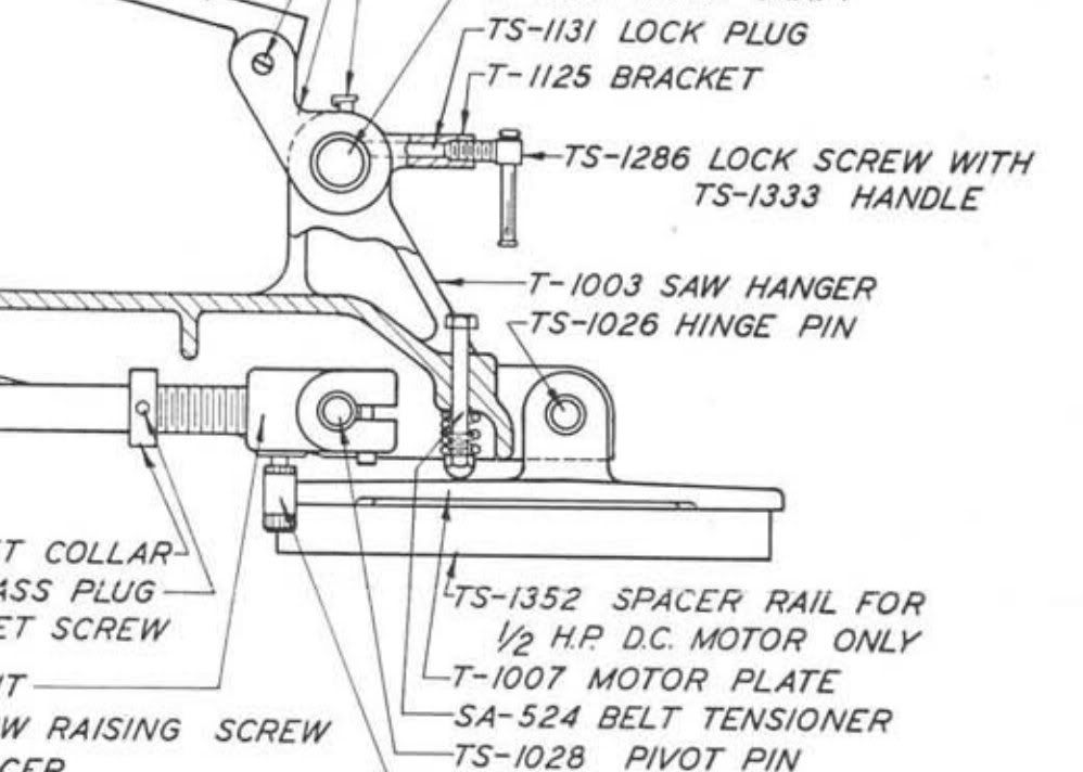
Lastly (for now!) the belt tensioner SA-524 looks to me like a long bolt with a spring and an acorn nut on it. I don't seem to have any of these parts so would appreciate any insight into their size. Is it a standard bolt or something custom?

Image

I do seem to be accumulating a pile of small parts that I think are going to wind up being 'left over', so I will flash a photo of these at some point!

Cheers,

Dan
crzypete
Posts: 1691
Joined: Thu Dec 16, 2004 10:45 am
Location: New York State
Contact:

Post by crzypete »

Dan, It looks like you are on the home stretch!

The batter gage support looks like you do have all of the parts. All of the fancy footwork is very similar to the camming action on the table mount that you just adjusted- The batter gage needs to be parallel to the blade and the set screws and stuff give you adjustment to make it so.

I am not sure what the part of top is.

The raise/ lower handle is correct, it is designed so it will disengage so you can hold a very precise position- ie the weight of the handle will not try to pull it of of position if it were positioned at 3 o'clock.

I never like the tensioning screw springy thingy on the G4's. I always found that the motor tended to bounce and cause vibration. Hammond must have agreed as the G100 has a fixed motor mount. I have solved this in the past by tapping the hole that the bolt is supposed to go through and using a bolt to press against the motor mount in order to tension the belt.

Pete
Daninvan
Posts: 50
Joined: Mon Oct 05, 2009 8:55 pm
Location: Vancouver BC

Post by Daninvan »

Wow! All that to keep the batter gauge square - you are right they DID think of everything!

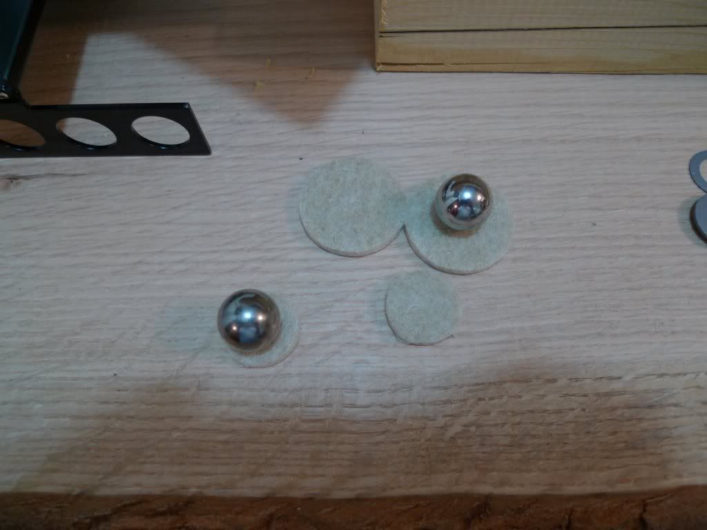
Back to the felt washers on the middle ball bearings, I'm thinking the ball bearing cage will be a bit rattle-y without them. So I thought I'd drill a 5/8" hole in a round felt that is used to go under furniture, etc.

Image

I took the saw back apart this weekend and my son and I moved it from the detached garage down into my basement shop. I hope to get the wiring taken care of next, should be pretty simple, but with a dozen trips to the hardware store if my typical luck prevails, then I'll put it back together for keeps.

More questions to follow, I am sure.

Dan
Daninvan
Posts: 50
Joined: Mon Oct 05, 2009 8:55 pm
Location: Vancouver BC

Post by Daninvan »

Working on the wiring tonight. I'm wiring the motor for 240V, using a 240V plug that has two conductors and ground on it.

I'm puzzled over how 120V was originally provided to the plug underneath (presumably it's for the lamp?), since there is no neutral wire. I'm guessing originally they just used ground as the neutral, or brought the neutral over to the saw somehow? Anyone know?

I am thinking I'll buy a transformer to give me the 120V. Of course, I need to track down a lamp before this will be anything more than theoretical!

Dan
crzypete
Posts: 1691
Joined: Thu Dec 16, 2004 10:45 am
Location: New York State
Contact:

Post by crzypete »

Hey Dan,

Running a separate neutral or using a transformer is definitely preferable over the using the ground.

Originally I am not sure what they did, but one option was using a 220v lightbulb- kinda scary when that badboy breaks!

Personally I am not wild about the lights on these saws. As a user who is not cutting small items like type, I find myself constantly bumping the light with bigger stock. I can check my inventory for a spare lamp, and I definitely have a suitable transformer just removed from my Oakley edge sander, but as I said, I would not go down that path- been there done that!

Pete
Daninvan
Posts: 50
Joined: Mon Oct 05, 2009 8:55 pm
Location: Vancouver BC

Post by Daninvan »

Pete,

Thanks for the insights on the electrics. I'd still be interested in a lamp for 'completeness', and if you have a spare we should talk, but I won't hold too many expectations for it in terms of actual use.

The felt washers didn't work, the hole in the middle was not big enough so I just went ahead without them. The sliding table does rattle a bit as I had feared, but I think I can live with it. If I decide later I can't, I'll try drilling full 3/4" holes in felt.

I took the saw apart and moved it from my garage into my basement shop. I started to reassemble it for keeps, and discovered a couple more missing parts, as well as several parts with damaged threads that I could not repair myself. So I have some stuff on order at Fastenal and some parts at the machine shop to be repaired. Right now I am stalled until Monday when it should all be ready.

Thanks for all your help so far!

Dan
Daninvan
Posts: 50
Joined: Mon Oct 05, 2009 8:55 pm
Location: Vancouver BC

Post by Daninvan »

Got back at it today after picking up all the stray parts at the machinist's yesterday. As it gets closer to done, most of the parts I though were going to be left over have in fact been used up. There will still be a few odds 'n ends though, but I'll save my questions on them until I know for sure what is left over!

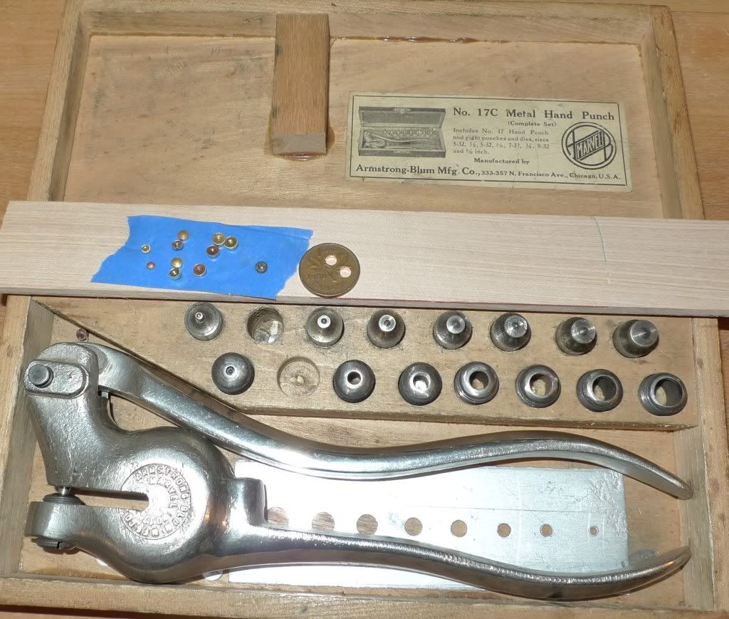
First step was to make up some new brass plugs for under the set screws on the arbor. I had lost one of the originals, so I made up a few of different sizes just for fun, using the old punch that belonged to my grandfather.

Image

Unfortunately I managed to somehow bend one of the taper pins that is used to hold the arbor assembly to the saw, so it's back to the machine shop tomorrow. Sigh.

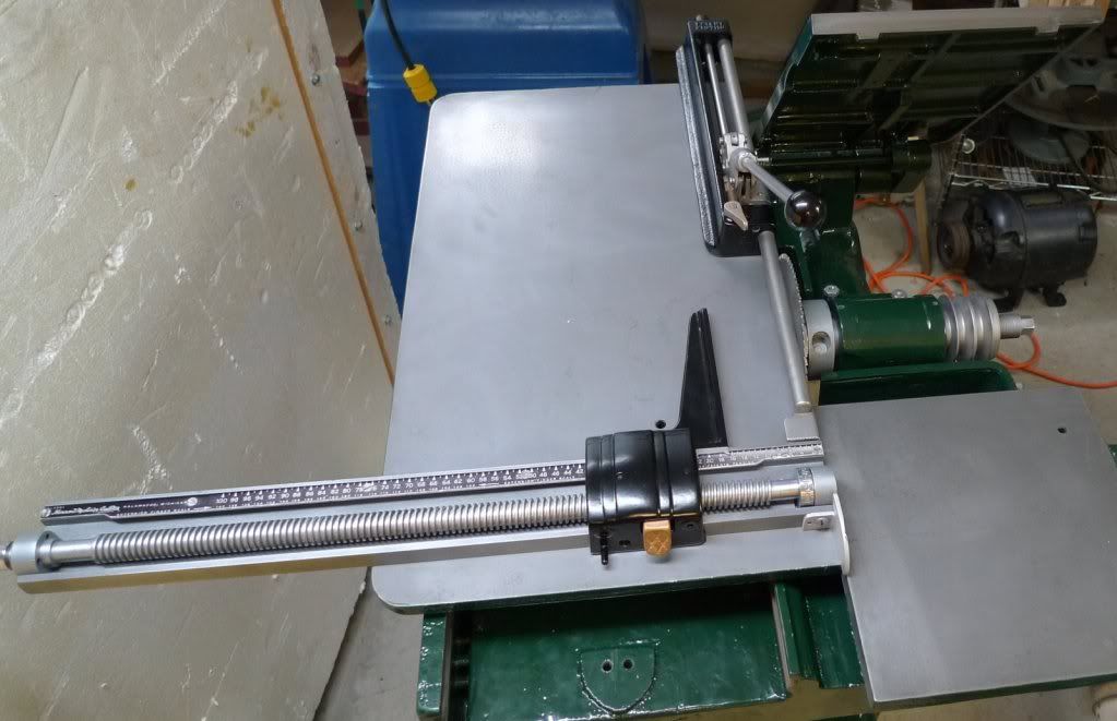
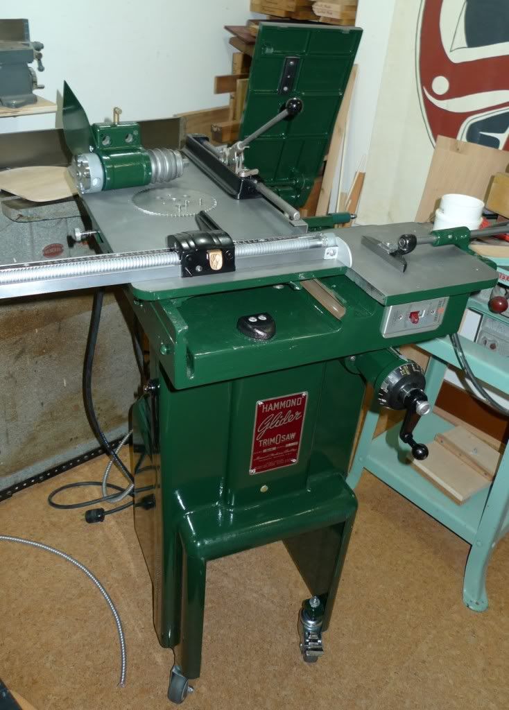
I've pretty much got the whole thing assembled, I think the only piece I am missing now is the thumb screw that holds the batter gauge in position. I do have the chip bucket and the handle, I just haven't figured out how to use it with the saw being on casters. I also have the blade guard, I need to get it welded up since it is cracked in two. New blade on order from Forrest.

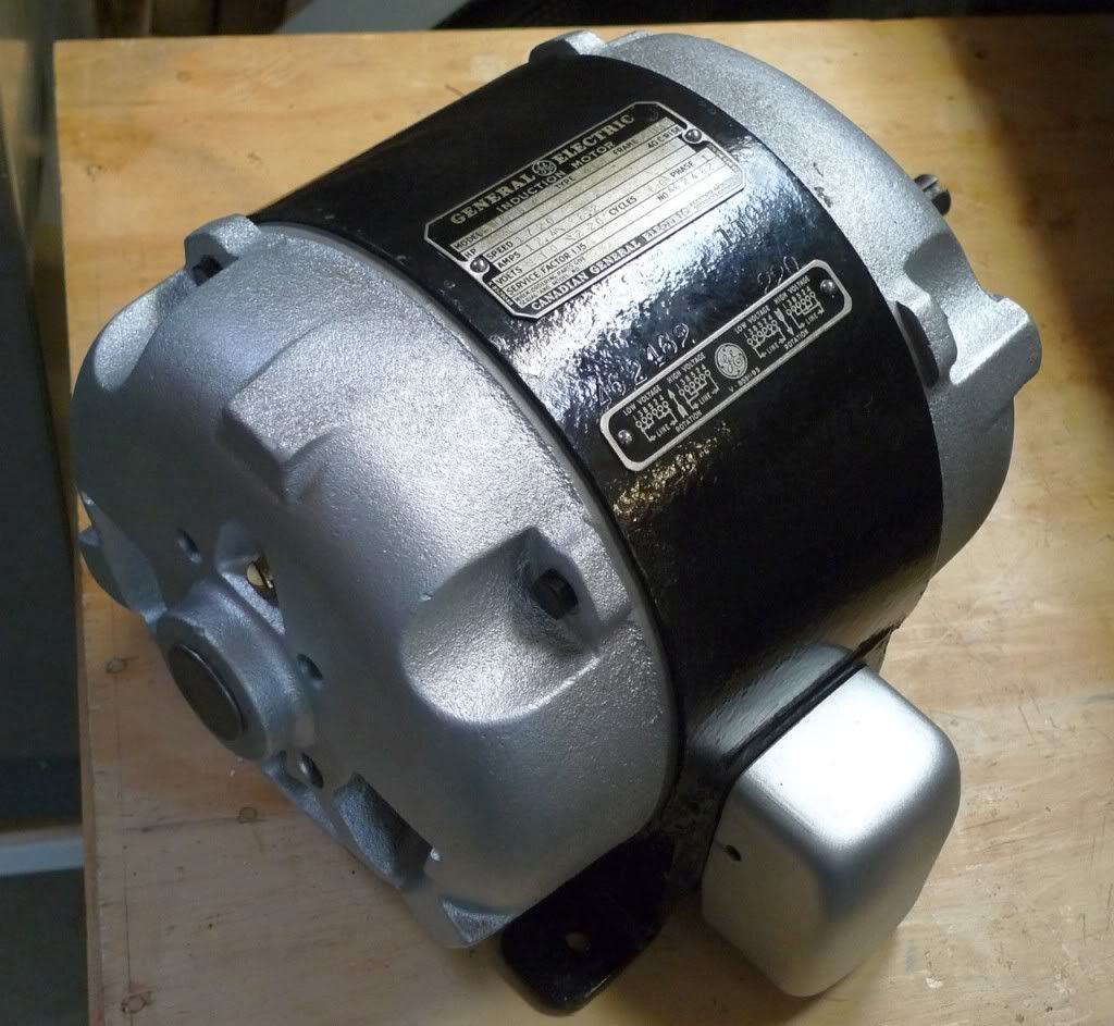
I still need to go through the motor, hopefully just a day's task! But I know it runs.

Image

A couple questions though:

What length belt should I get?

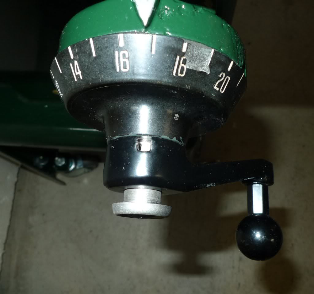
The following photo of Rick's machine I took from this http://www.machinejunkie.com/forum/viewtopic.php?t=723 thread. The photo shows that the dial is held in by a knurled threaded knob/bolt/pin. Is this typical of older Gliders, the reason I ask is mine was similarly equipped when I got it, I replaced the knurled knob with an Allen screw. If these were used, why is the easy adjustability they imply required?

Image

Dan
crzypete
Posts: 1691
Joined: Thu Dec 16, 2004 10:45 am
Location: New York State
Contact:

Post by crzypete »

Wow, it is really close to completion. You must be tasting the end by now. replacing the brass protectors is a good call. Without them the setscrews definitely can do some damage. I like you material source!

The knurled knob on the pica scale is original and was probably important for certain printing applications where you would want to zero the graduated raising dial so you could precisely cut a depth. In my world, it is something i never think to need nor can imagine using. The thumb screw has never been in my way, but a set screw would be just as fine for me.

Also, about those taper pins which hold the arbor to the raising and lowering trunnion. They have a nut on the top of them which is meant for removal. Often people have the urge to tighten them, thus pulling out the taper pin. They should be snugged down, no more.

Pete
Daninvan
Posts: 50
Joined: Mon Oct 05, 2009 8:55 pm
Location: Vancouver BC

Post by Daninvan »

Close, and getting closer - and taper pin crisis resolved!

Image

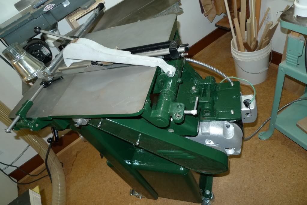
The blade guard is giving me some problems now. I had it rewelded as it was broken apart only about an inch from the pivot. Now it does not seem to align well with the blade. It's actually parallel to the blade, just too far to the right I think. When I raise the blade, it scrapes the inside of the blade guard.

I suspect when they welded it they built up some material on it that interferes. Question is, where should the guard be, relative to the blade?

Image

Dan
crzypete
Posts: 1691
Joined: Thu Dec 16, 2004 10:45 am
Location: New York State
Contact:

Post by crzypete »

Hi Dan,

Sorry for the delay in responding. I am not really a guard user, and the two saws that are my daily users are both G100's which sport a different guard- even if I had them installed. I do believe it is sitting too far to the side, but cannot get a photo to show you how it should be. My guess would be centered.

Anyone else?

Pete
Daninvan
Posts: 50
Joined: Mon Oct 05, 2009 8:55 pm
Location: Vancouver BC

Post by Daninvan »

Pete,

I just 'machined' the surface of the guard where the weld was interfering with the fit. Used a sanding drum on my drill press to 'machine', worked well enough. I also noticed that the screw holding the guard in place was bent. Fixing these two things seems to have solved the problem.

Got the motor rebuilt, blinged it up a bit.

Image

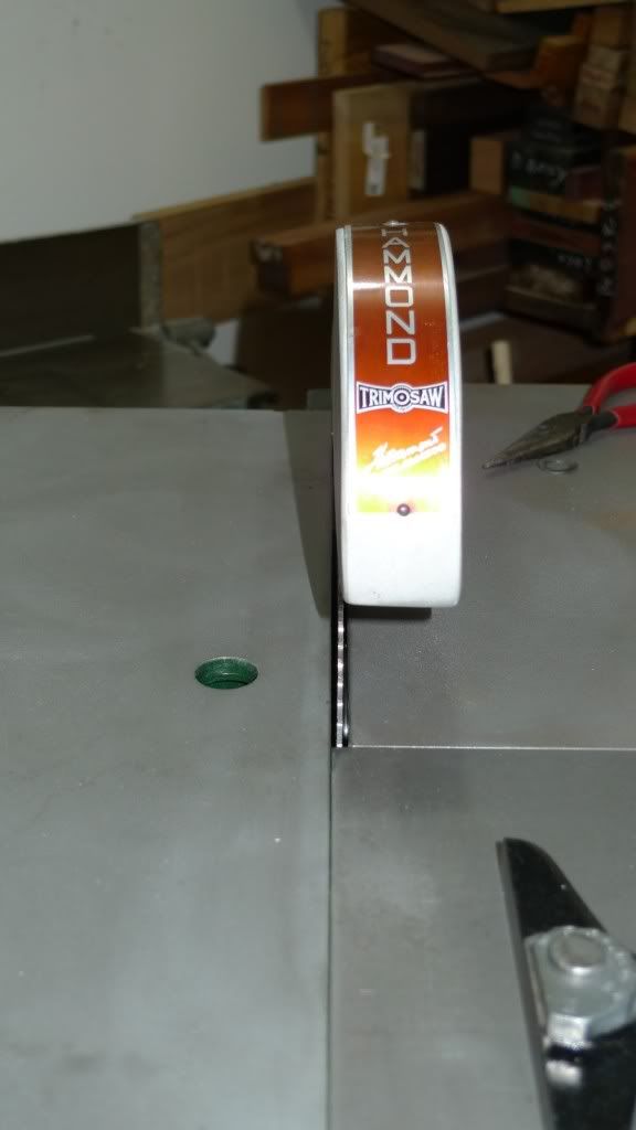
Now I just need to buy a couple belts, do the last bit of wiring and fire it up! Waiting for a table from a member here should be on it's way to replace the small one that got lost.

Image

Thanks again for all your help as I went through the resto, I couldn't have done it without you!

Cheers,
Dan

PS Thought I'd just add a couple things.

48" belts fit my machine. I hope the hardware store will take back the 49" pair I also bought!

I have a Radio Shack Sound Pressure Meter so I thought it would be fun to take a reading on the Hammond. It's 73 dB, it's one of the quietest tools my shop. For comparison, my Powermatic 66 is 92dB, my Dewalt 735 planer is 114 dB, and my two bandsaws are both around 75 dB.
Post Reply