Tannewitz 30" PH Band Saw

techniques and projects: share and learn

Moderator: nektai

chathamworkshop

Tannewitz 30" PH Band Saw

Post by chathamworkshop »

The band saw has been sitting in the shop for months patiently waiting to be restored. For a 60+ year old machine, it is in remarkable condition. Everything works well, electrically and mechanically, and all parts right down to the nuts and bolts are there. The motor is a 3 HP 860 RPM direct drive Howell, and the tires are in good shape with no cracks or wear marks. When the saw was turned on, there was very little vibration. There is some minor surface rust on some non-painted surfaces that will have to be cleaned and the entire saw needs to be painted. The paint on the surface of the main frame is badly checkered, and peels off easily. The good news is that there is almost no rust under the paint and it will be easy to remove. So here begins the saga.
Image
Image
Image
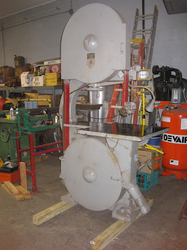
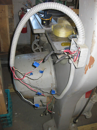
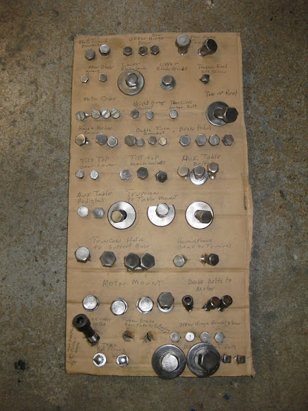
I decided to remove the starter and enclosure first as the support bracket was removed when I bought it and the enclosure was hanging loosely from the armored cable that attached to the body. The thing just bugged me hanging there. I tagged all the wires going to the starter and remote switch and took pictures of the connection terminals in both for future installation.
Image
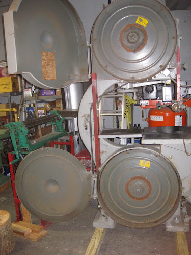
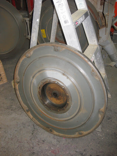
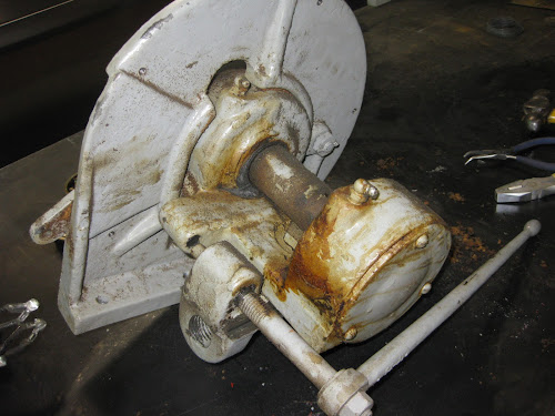
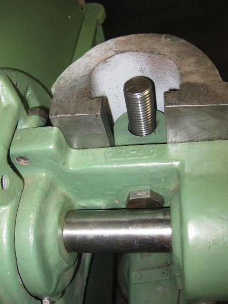
Next came the wheels. The upper wheel was anchored to the shaft with two ½” set screws. These were loosened and a wheel puller attached to the wheel hub and shaft. The wheel came off easily for the first few inches, and I then manually pulled it off the last inch or so. I did not want to risk having the wheel fall off while I was busy with the puller.
Image
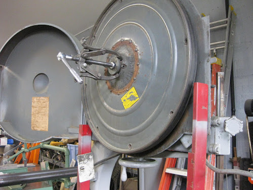
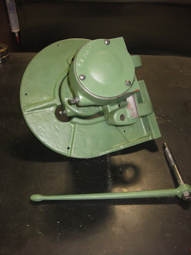
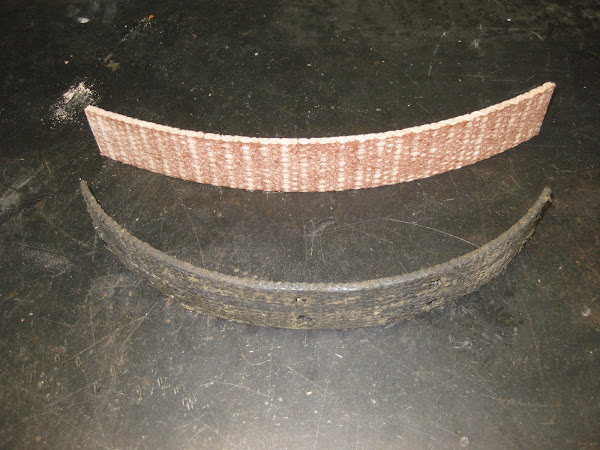
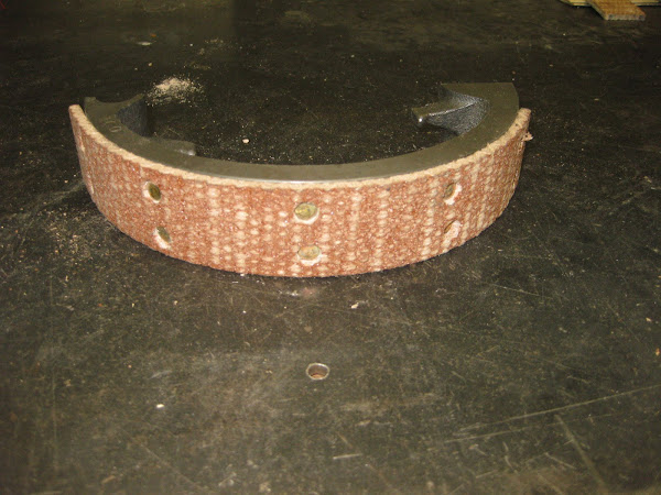
I was surprised at the size of the 8-1/2” diameter brake drum and brake shoes which could have been used in a small car. The construction of the wheel is solid and is interesting with the steel outer frame joined to the inner cast iron hub and brake drum using both welding and rivets. The outer perimeter of the wheel has eight 5/8” threaded holes that are made to accommodate the tire installation tools for a new tire. I am lucky I will not need to do this, as a tire will cost $300 and I would have to purchase or borrow the eight installation tools.
Image
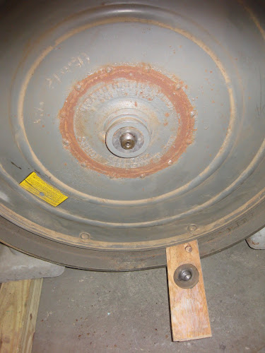
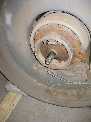
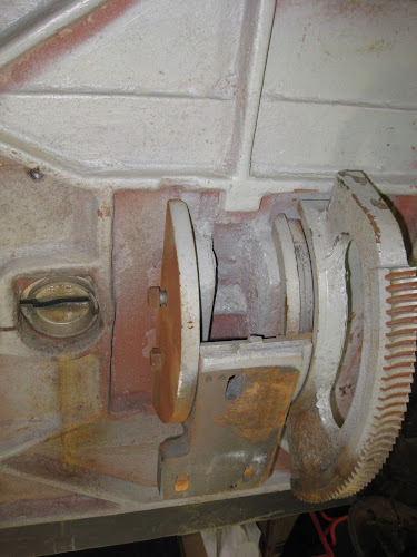
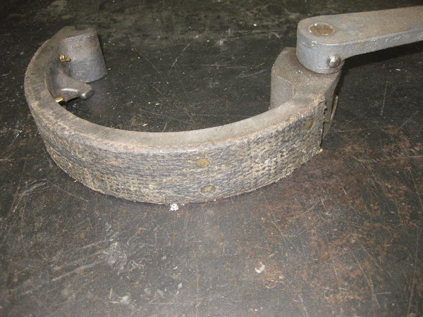
The lower wheel had a cap nut that was removed counter-clockwise. It also had too set screws that were loosened and the wheel came off easily with the puller. With the wheel off, I had a view of the brake assembly, and was surprised to see that the brake cable was badly frayed and only one strand remained attached to the brake actuator. This was going to fail with just a little more use.
Image
Image
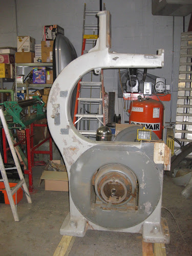
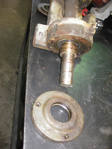
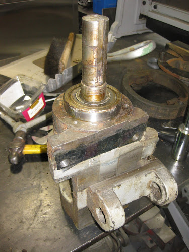
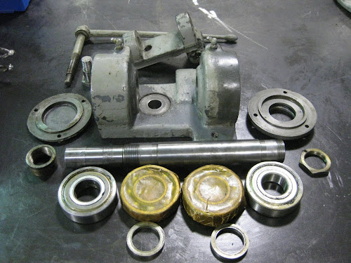
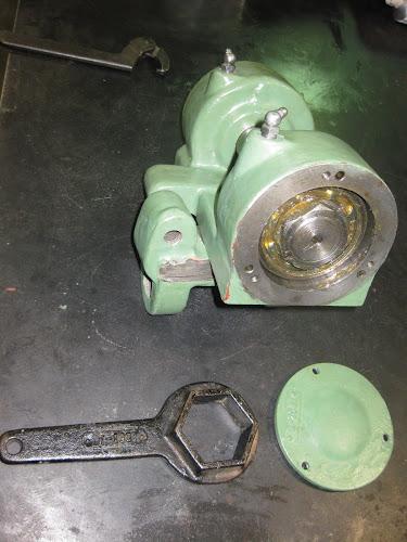
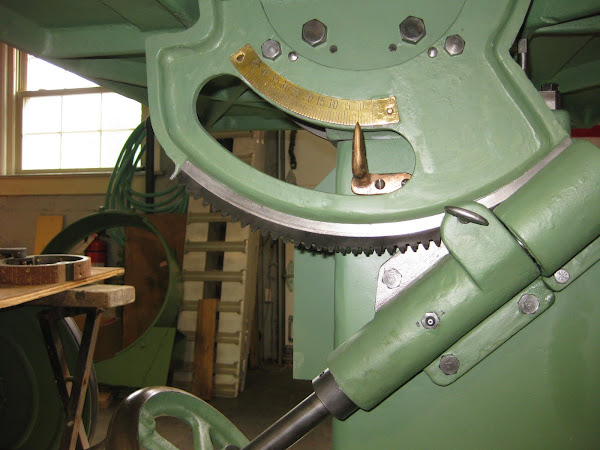
The upper door and wheel well were removed which gave me easier to access to the upper wheel arbor and bearing housing. After removing the brake cable from the brake lever, the assembly came off by simply cranking the whole unit up to the top by turning the revolving handle for blade tensioning mechanism and then lifting it off the saw. I had to use a small ladder to give me comfortable access to the assembly at that height.
Image
Image
Image
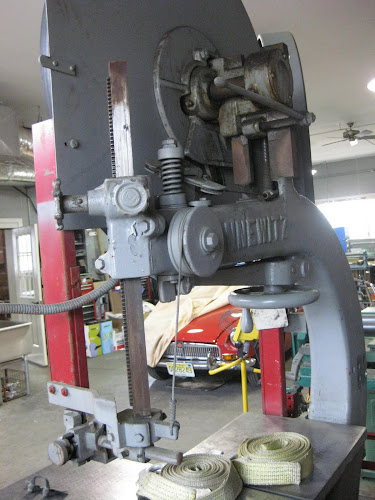
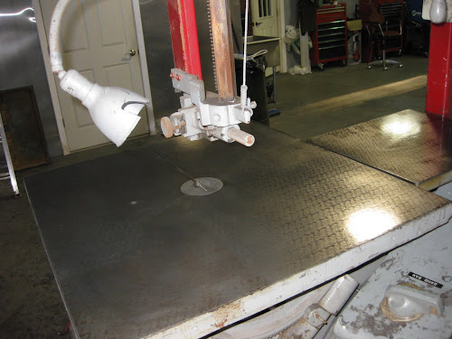
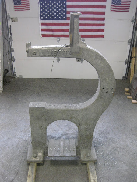
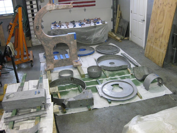
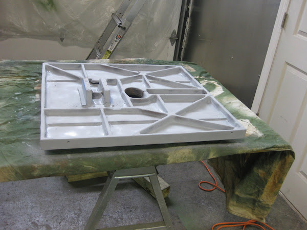
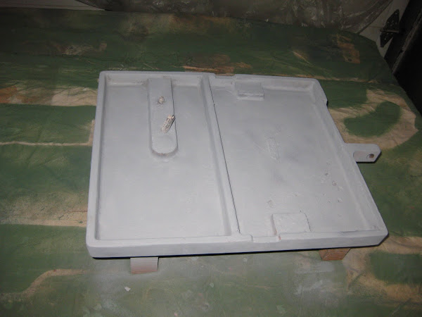
Removal of the table, tilt mechanism and trunion came next. First, the auxiliary table was removed. The cranking mechanism for the tilt table was then removed to get better access to the three bolts that hold the trunion and table to the pedestal on the band saw frame. These were removed and the table and trunion were lifted off as a unit. The table was then inverted and the trunion was removed.
Image
Image
Image
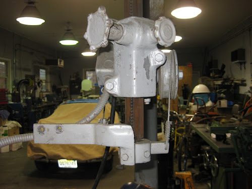
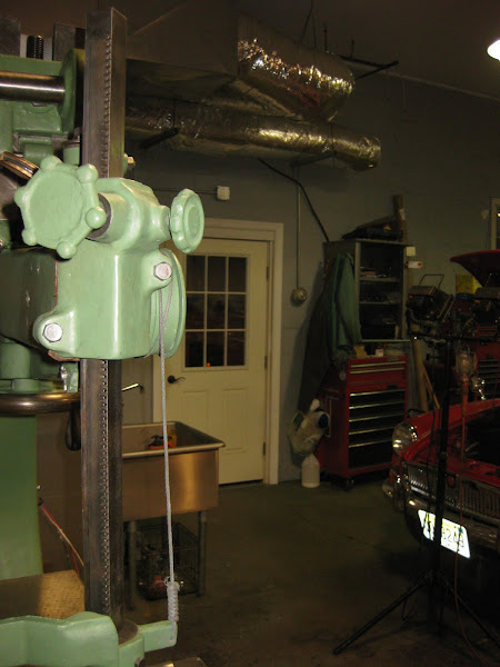
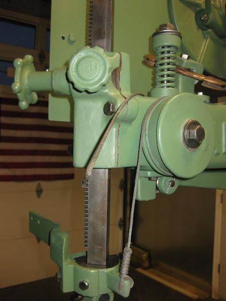
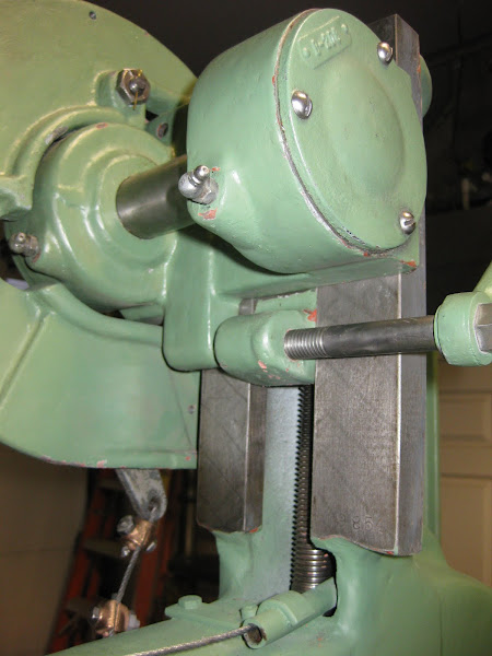
The upper and lower blade guides were removed and then the spring powered tension reel and cable that supports guide post rack and pinion mechanism. I was careful removing the reel to allow the cable to retract slowly. An interesting side note is that the two housing units that enclose the guide post used babbit as a bearing surface. I could not understand why they were so heavy when I removed them!
Image
Image
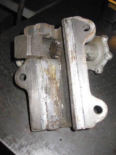
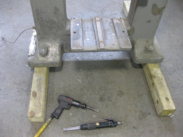
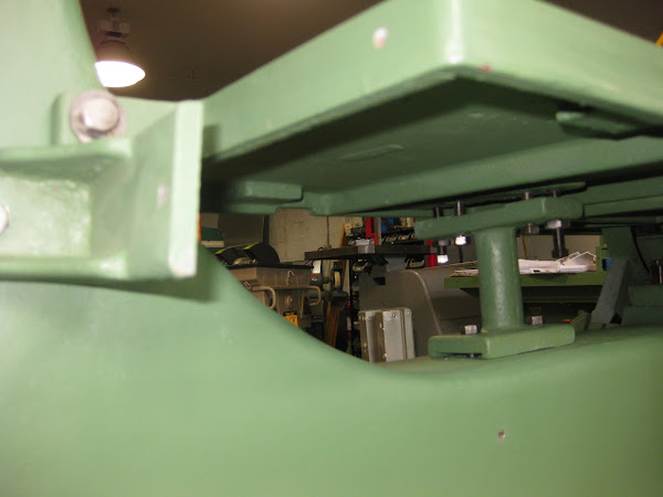
During the removal process, I paid particular attention to the cable network for the brakes. There are two systems: One that is operated by a foot pedal that actuates the cables going to both the upper and lower brakes. The second system uses the start/stop switch lever which is attached to a cable that goes through the lower part of the frame to the brake pedal. Pushing the lever depresses the brake pedal mechanism and actuates the cables that go directly to the upper and lower brakes as if you were stepping on the pedal. This cable has a couple pulleys and transitions located on the underside of the band saw. I could only see it by using a mirror and light. The only way to access this area is to either lift the frame up with a shop crane, or tilt the frame on its side. My inspection showed the cable to be in good shape, so I did not touch this. I did remove the cable network going from the pedal to the upper and lower brakes. It is a bit complicated, so I took plenty of pictures to help out with reassembly.
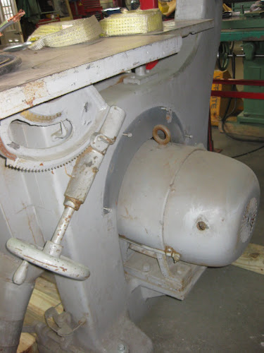
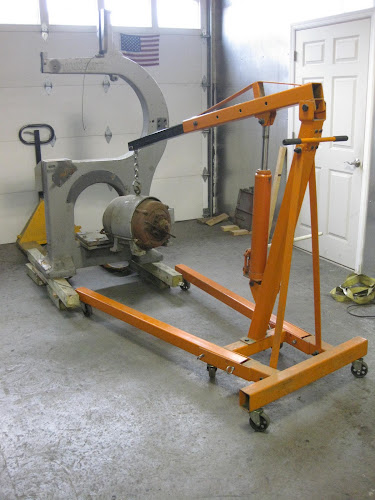
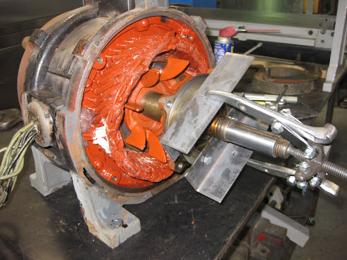
All that remained was the motor. I removed the rear cowling on the motor which gave me access to the two rear mounting bolts. The front bolts were also removed and the motor was lifted from its resting place with a shop crane.
Image
Image
Image
Image
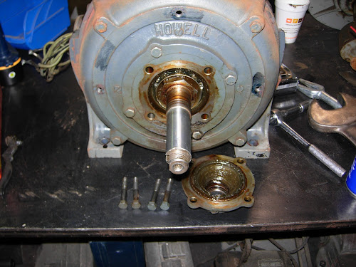
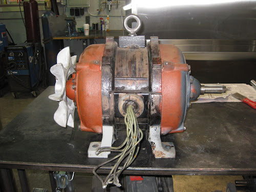
I have to say, that this is the largest 3 HP motor I have come across. It easily weighs 350 pounds, and looks more like a 20 HP motor until you read the identification plate. I was very impressed with the external condition of the motor. A foxtail brush and little compressed air and it looked pretty good for a 60 year old work horse.
Image
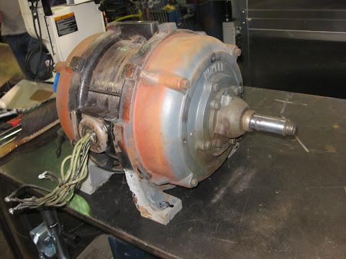
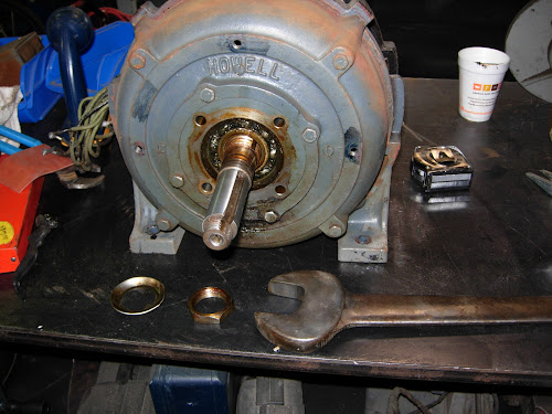
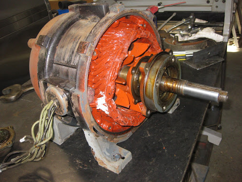
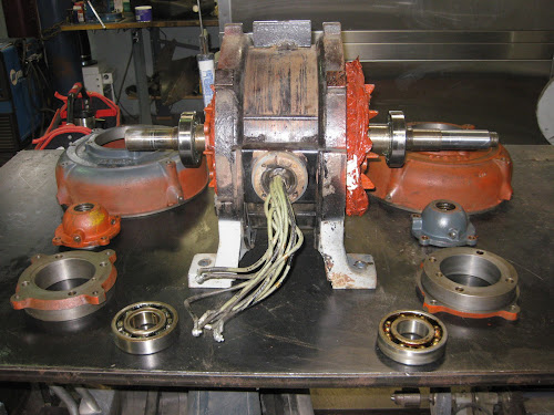
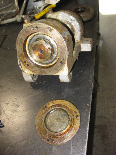
I decided to disassemble and clean the motor, replace the bearings and reassemble and test the motor before going further with the remaining restoration. I always want to make sure that there are no problems with the motor at this point in the process. No use leaving this out of the restoration process when it might need some work. The only way to really know is to disassemble it, and as long as you have gone that far, you might as well replace the bearings.
crzypete
Posts: 1691
Joined: Thu Dec 16, 2004 10:45 am
Location: New York State
Contact:

Post by crzypete »

Oh, this is definitely going to be a fun watch for me. I have a very similar 30" Tanny bandsaw. Some differences that I see between this saw and mine.

-Mine is not direct drive :( It was intended to have a reeves drive that was long gone when I bought it. Towards this end, the main casting is completely different- no big opening to allow for the motor.

- Mine has a rectangular guide post that is square to the guides rather than a square one that is 45º to the guides. I believe this may be a slightly newer indicator for my saw.

- I am missing the upper brake :( the lower one stops it fast enough, but the upper brake would be nice in case I ever broke a blade, which I never have done, so I guess it is not that big a deal.

-My lower wheel attaches just like the upper one- with setscrews. I am guessing this may be a factor of the difference between not having the direct drive motor.

-Lastly, if I am reading it correctly, your tannewitz badge is cast into the saw, while mine is a cast plate bolting it on.

Some questions.
-do you know the year of manufacture?
-how is the table condition? fancy Tannewitz grinding marks?
-Your intentions, Is this a keeper?

I think the motor is so heavy because of the low RPMs, I believe (perhaps incorecctly) that there is some relationship between slower motors and bigger windings. Also something about higher torque.

I am sure this saw is going to be beautiful once you are done. I find the 30" Tannewitz's to be simply awesome machines. Incredible capacity and power in a reasonable footprint. I am eager to follow along!

Pete
chathamworkshop

Post by chathamworkshop »

Pete: This is a fun project, so far, but I have not yet hit any obstacles. The time consuming, more boring part of a restoration lies ahead of me with cleaning the parts, stripping off the old paint, and the preparation for painting. Disassembling and assembling a machine usually goes pretty quickly.
The serial number for the saw is 9854, which according to the OWWM Knowledge Base, makes its manufacturing date probably in 1947. So it is a spry 64 years old, but “well preserved.” If you have a date on yours, it would be interesting to compare the differences between the two. There are probably a few more items. For instance, as you had mentioned, the Tannewitz name is cast into the upper arm of my saw. I do not think this is as cool as the nameplate that your saw has. I think the name plate looks more classy than the cast, raised name.
Another thing that would be interesting thing to investigate would be to find out when Tannewitz started using hydraulic braking on their band saws. I have heard mixed reviews on the larger saws when it comes to maintenance. The brake cylinders seem to leak and the corrosive brake fluid can play havoc with the paint. For my two cents, the hydraulics is overkill. The two massive brake drums and foot pressure through the cables can stop the wheels in a few seconds.
The motor is set at 860 RPM, which is not as low as some RPM options offered by Tannewitz. I agree with you that the size is more related to torque production. The heavy band saw wheels, a high torque motor and low RPM’s make the saw an excellent flywheel for plowing through thick wood. It seems like the trend in modern day band saws is geared more toward high horse power and speed. Not sure where the right answer lies, but for what I do, I will take torque any time.
You asked about the tables and the characteristic grinding marks that are the trademark for Tannewitz quality. I have attached a picture that will show you the condition of the tables. There is some wear, but after all these years, that wonderful pattern still stands out.
As far as my plans go with the band saw, I plan to keep it and match the paint that I have on the J 250. They will make a fine pair. My business has really turned around in the past few weeks, so I plan to put these machines to work!
Image
chathamworkshop

Post by chathamworkshop »

The disassembly of the motor turned out to be pretty straight forward. I was a bit intimidated at first by its size and because the construction was different from other motors I have worked on. First, the fan was removed from the rear of the motor. Two bolts were loosened that clamped it to the shaft. I was then able to pull it free from the shaft by hand. There are 12 bolts that hold the front and rear sections of the motor together. The inner four bolts hold the grease cups for the bearings, the center four hold the bearing housing, and the outer four secure the bell housing. First, the four bolts that hold the grease cup on the drive side of the shaft were removed. Behind that was a 2” right hand threaded nut and retaining washer. The washer was secured to the shaft by a tab that fitted into a groove in the shaft, and the sides of the washer were bent around the edges of the nut. This holds the nut in place and keeps it from backing out while the motor is running. I used a drift to bend back the sides of the washer. Then used a 2” open end wrench on the nut and secured the rear shaft with a crescent wrench that was held in place against the woodruff key that secured the fan. The nut came free with some pressure.
Image
Image
The 8 nuts that hold the bearing and bell housing were removed. When the bell housing was removed, I was surprised to see that the internal guts of the motor were immaculate. There was not a speck of dust. Also, there was an identical grease cup on the inside of the bearing. Both cups had grooves cut on the inside lip of the cup that the shaft protruded from. The gap between the lip and shaft is about .005”. When the bearings and cup are packed with grease, grease fills the grooves which act as a seal against the shaft. This explained why the motor was so clean externally and internally.
Image
My wheel puller was not long enough to get a grip on the bearing housing, so I improvised with two pieces of angle iron. Two holes were drilled in each piece that lined up with the threaded holes on the inner grease cup, and bolts were run through the angle iron and attached to the grease cups. A hole was also drilled into the side of the angle iron to allow the puller a place to grip. The bearing, bearing housing and grease cup came out easily with the wheel puller.
Image
Removal of the rear bearing was identical to the drive end, except the angle iron was not used to pull the bearing because the shorter shaft allowed the puller to grip the bearing housing. The bearings were unsealed 308’s. The hefty armature was pulled out and felt like it weighed 40 or 50 pounds. The shafts were cleaned and new unsealed bearings were pressed on the shafts after both bearing grease cups were put in place.
The picture below shows the mostly disassembled motor with new bearings on the armature. The inner grease cups were photo shy and hiding inside the motor cavity. Reassembling the motor went fairly quickly. The bearings and grease cups were repacked with grease, which took about a ½ cup for each bearing. The motor was bench tested for 15 minutes and ran cool and quite.
Image
Image
crzypete
Posts: 1691
Joined: Thu Dec 16, 2004 10:45 am
Location: New York State
Contact:

Post by crzypete »

My saw is a 1952 (serial 11591) and has the foot applied brake- I am definitely happy about that as I have heard similar things about the hydraulic ones.

The model of my saw is a PV-1 as I mentioned it is a belt drive that originally had a reeves drive set-up. This is a bit of an oddity, but could be useful for someone who was dead set against 3Ø conversion as you could add a single phase motor quite easily.

Nice job on the motor rebuild, that is simply one more thing that you should never have to touch again. Also nice job on the pulley extenders, I love it when a little ingenuity solves a major problem!

What's the next step?

Pete
chathamworkshop

Post by chathamworkshop »

From what I have read, your PV-1 is a rarity. I would love to see a picture of one with the Reeves drive. That variable speed option would add some real versatility to the machine.
I have now started to clean and disassemble the upper wheel bearing housing. I want to get this done before starting the drudgery and time consuming work of paint stripping and cleaning of the rest of the machine.
nektai
Posts: 1019
Joined: Fri Dec 17, 2004 9:34 am
Location: Long Island, NY
Contact:

Post by nektai »

I wanted to post my experience with the hydraulic brakes. Mine are in need of a rebuild again! The pistons on the lower wheel have bound up and the brake was partially engaged. My solution was to remove the assembly. Ugly but effective.

I would much prefer the mechanical brake system!
chathamworkshop

Post by chathamworkshop »

Just out of curiousity, could you give the year your band saw was made. It would be interesting if we could zero in on a date when Tannewitz started making the hydraulic brakes.
nektai
Posts: 1019
Joined: Fri Dec 17, 2004 9:34 am
Location: Long Island, NY
Contact:

Post by nektai »

It's a PHE 15061. Is that 1961?
crzypete
Posts: 1691
Joined: Thu Dec 16, 2004 10:45 am
Location: New York State
Contact:

Post by crzypete »

late 1965

http://wiki.owwm.com/Default.aspx?Page= ... eSupport=1

I would guess that the hydraulics became an option at some point rather than there being an exact date that they started using them.

Pete
chathamworkshop

Post by chathamworkshop »

The next part of the restoration process involves the cleaning, disassembly and replacing the bearings of the upper wheel bearing housing. But before getting into this, I thought I would mention a technique a friend gave me about organizing the fasteners you remove from machinery during disassembly. He does this when he restores cars and calls it a story board. This technique is so obvious, that I am kicking myself for not thinking of it. I used wrap tape around the bolt or nut describing where it came from or putting them into boxes and jars, that had the area where they were removed from written on the container, and then had many head scratching moments trying to get the right part to the right location.
The method is to take a large piece of corrugated cardboard, let’s say 12” by 24”. When you remove a bolt(s) from a particular area, take a box cutter and punch an “X” into the corrugated large enough for the bolt to be pushed through. The corrugated will hold it in place well enough so it will not drop out. Put the nuts and washers on the opposite side of the corrugated. Write the name of the area that it came from above the fastener. Start the process from the upper left side and progress to the right side then proceed down until you fill up the space. Now you have everything you need captured on the story board. It gives you the parts and the order on which they were removed. I have done this a few times and what a time difference it has made in reassembling the machine.
Image
However, I digress. Back to disassembling the upper wheel bearing housing.
The first order of business was to remove the cast plate that supports the upper wheel well housing and brake mechanism. This came off by removing two ½” bolts. The handle that does the blade tracking was also unscrewed. Next, the three bolts that attach the covers for the front and rear bearings were removed. This gave access to the bearing retainers. Both retainers were identical to what was used in restoring the motor on the J-250 table saw. The rear retainer was a 1-3/4” diameter nut, with a clockwise thread. The nut also had a horizontal split on one of its edges that was tapped to take an Allen set screw. When the screw is tightened, it clamps down enough on the threads to keep the nut from backing out. I used the special Tannewitz wrench I acquired at an auction that was made to remove the nut. The socket portion of the wrench extends forward enough to reach inside the housing to get at the nut. I forgot to put the wrench in this picture, but included it in a later picture. If anyone wants to borrow the wrench, just let me know. The retainer for the drive end of the shaft was a left hand threaded sleeve that was removed with the same flexible spanner wrench I used on the table saw.
Image
Image
The shaft and front bearing were pressed out from the rear, and the rear bearing easily came out with a few taps with a large brass drift. There were two spacers behind each bearing that slid off each end of the shaft. The 3/4” shoulder bolt that attaches the blade tensioning sliding bracket to the bearing housing was now removed as earlier access to the bolt was blocked by the shaft. Both bearings were the same with number 77307.
Image
The parts were cleaned, and I decided at this point to prime and paint the parts. I figured I might as well get the whole assembly completed while everything was still fresh in my mind, rather than to wait until the end to do the painting.
Image
Once the paint was dry, the spacer was put on the drive end of the shaft and a new bearing was pressed on the shaft. At this time, the shoulder bolt was put through the hole in the bearing housing and screwed into the blade tensioning sliding bracket. The bearing and shaft were then pressed into the bearing housing. The second spacer was put on the rear end of the shaft, and the new rear bearing was pressed onto the shaft and housing. The threaded sleeve was put on next and tightened, followed by the 1-3/4"” nut. The bearings were packed with grease and then the end caps were screwed back on.
Image
Image
Next comes the tedious, time consuming and boring part of any restoration. Cleaning and stripping the paint from all the parts and surfaces.
Last edited by chathamworkshop on Sun Apr 24, 2011 8:55 pm, edited 1 time in total.
crzypete
Posts: 1691
Joined: Thu Dec 16, 2004 10:45 am
Location: New York State
Contact:

Post by crzypete »

OK, that is one slick tip, and quite simple! Yes Indeed I will be stealing it....

And boy does that bearing housing take me back. It must be over 10 years ago that I rebuilt my Tannewitz. What a saw!....Glad I don't have to do it again!

The one piece of advice I can give you that I learned from my rebuild is that you should ignore the lower front of the main casting- the part that sits behind the disk of the wheel. I worked hard to get that area just as cherry as the rest, but it hasn't seen the light of day in ten years! I wasn't thinking.

Pete
chathamworkshop

Post by chathamworkshop »

Pete: Glad you like the the story board. You will find it a timesaver and memory jog.
I have already removed the paint from the main casting with a needle scaler, but when it comes to preparation, I will skip using bondo and glazing putty.
Last edited by chathamworkshop on Sat Apr 23, 2011 8:41 pm, edited 1 time in total.
crzypete
Posts: 1691
Joined: Thu Dec 16, 2004 10:45 am
Location: New York State
Contact:

Post by crzypete »

I was not saying to skip the bondo completely- the exposed parts of my saw are some of the sweetest lines out there and definitely worth the time spent bondoing, I just bondoed the hidden parts as well :oops:

It always up to the painter though......

Pete
chathamworkshop

Post by chathamworkshop »

For paint removal, I decided to tackle the main casting first. I started out using a pneumatic chipper, but the paint was so loose from checking, that the needle scaler turned out to work more efficiently. The work only took about an hour and a half. A final cleanup of the casting was done using a right angle grinder with a cup brush. It is hard to see from the picture, because the floor is painted the same color as the paint chips, but there was probably a pound of chips around and under the casting when I was finished.
Image
Image
Next came the stripping the paint off of all the various small parts that could be fit into a sandblasting cabinet. Unlike doing the main casting, this took several hours to get through. Shafts and other non-painted surfaces such as the trunion were cleaned with a wire wheel.
Image
The band saw wheels, wheel wells, doors and other large parts were done outdoors with a cheap Sears siphon sand blaster.
Image
Stripping of the paint also took off the bondo and glazing compounds that were on the main casting and all the small cast parts. This left ugly voids and uneven areas that needed to be smoothed over or filled in. I found this to be extremely tedious and time consuming. Several passes were needed with the glazing compound followed by sanding between applications. An equally meticulous chore is the taping of parts that had metal exposed for to metal contact and also the task of plugging exposed threaded and open holes for the bolts and shafts to keep paint from clogging these areas. I used rolled up newspaper to plug the bolt hole and stuffed newspaper into the lager shaft openings. The pictures show the main casting and all the parts prepped for priming.
Image
Image
crzypete
Posts: 1691
Joined: Thu Dec 16, 2004 10:45 am
Location: New York State
Contact:

Post by crzypete »

What an epic job of pant removal! This is on of those machines that just has so many big parts it is ridiculous.

I remember my Bondo job being extensive, but in the end the results were totally were it.

To plug holes for painting I am partial to these red plastic plugs I buy from mcmaster. They come in numerous sizes and are pretty darned cheap. Much faster than dealing with paper or tape. For specially sized holes, I;ll often wrap them with tape to make them bigger. I also often cut the lips of so they are flush and do not leave a shadow of lack of paint.
http://images1.mcmaster.com/Contents/gf ... er=7918376

hopefully this link will take you to the catalog page, if not it is page 3724
http://www.mcmaster.com/#tapered-plugs/=c66esl

ON edit, Ok it takes you to a universal plastic plug page- try the flexible plastic plugs link

Pete
chathamworkshop

Post by chathamworkshop »

Pete: Thanks for the "plug" for the flexible plugs. I'll get some with my next order with McMaster Carr.
chathamworkshop

Post by chathamworkshop »

Before priming, all the rusty/cruddy fasteners on the story board were cleaned on a wire wheel and the stage was set to get started on priming the parts.
Image
The area for painting was cleaned and dusted and the parts were wiped with a tack cloth, and then were laid out on canvas or newspaper. It took 5 rattle cans to prime the saw. On the larger pieces such as the wheels and wheel wells it was a two stage process. First priming one side, then flipping it over when it was dry, and doing the other side.
Image
When these were dry, the table and auxiliary table were stripped and primed. I used the needle scaler on the main table and a rotary brush on a right angle grinder for the auxiliary table.
Image
Image
Image
The parts were let dry for a couple days, and then were sanded lightly with 220 grit sand paper. The area was again cleaned, dusted and everything wiped down with a tack cloth. An HVLP sprayer was used to apply the top coat, which was a Sherwin Williams industrial lacquer. It is the same paint that was used on the Tannewitz J-250.
When I did a test spray on a piece of cardboard, I found that the paint was grainy, and dried in a matter of seconds. Also, the air coming from the sprayer was much hotter than I could remember when I painted the table saw. A friend took a look at the sprayer and commented that the filter looked like it might be clogged. He was right, and I was embarrassed! The filters were cleaned and some retarder/thinner was added to the paint. This time the spray was even and bright and dried in a few minutes. All the large parts were laid out on canvas with 2” X 2” wood strips under the parts to keep them off the canvas. The main casting stood on its own. I started at the back of the shop and worked my way forward, being careful as I painted that the hose did not touch the wet paint. The cycle was repeated on both sides until three coats were applied.
Image
There was not enough room to do all the small parts as the casting and large parts took up all the room available. The paint on the large items was allowed to dry over night, and I then cleared off the table and placed all the small parts on the canvas. There are a lot of areas that are difficult to reach with a sprayer, so I decided that it would be easier and quicker to paint by hand.
Image
The brake shoes were also put on the table as they had been cleaned and were ready for installation. These were not painted.
The shoes for the upper brake had seen quite a bit of wear and were saturated with grease. New brake lining was purchased from McMaster Carr and put on the shoes. The lower brake was in very good condition, and the lining was not replaced.
Image
The old brake liner was used as a template, and holes were drilled that were the same diamater as the rivet body. A larger countersink was then sunk over the smaller hole in the lining to accept the rivet head.
Image
Image
From the time I started stripping, cleaning and prepping the large parts, main casting and all the little parts, to finishing up with the priming and painting, 5 weeks elapsed. The disassembly only took about a week. Obviously, there were a lot of other things I was doing besides working on the band saw, but it gives you an idea where the labor goes when you restore machinery.
The fun part now begins with the re-assembly. I am keeping my fingers crossed that I can remember how it all goes back together!
chathamworkshop

Post by chathamworkshop »

The motor adjustment plate went on first. It has two 5/8” bolts that secure it to the base of the main casting. The holes in the plate are oversized for the two bolts which will allow minor adjustments of the motor and lower wheel to be made using two adjustment screws. These bolts were left loose for future adjusting.
Next the motor itself was mounted on the adjustment plate, and the four ½” bolts that secure it to the plate were tightened. The motor cowlings were put on before the motor was mounted. Note the brass pipe and fitting for lubing the front bearing. This was a surprise when the old paint was removed.
Image
Image
The main and auxiliary tables were put on next. I always like to put them on early during reassembly as they offer a place to put tools and parts. The main table was put on a table upside down, and the trunion and hemispherical worm gear for the table tilt adjustment were mounted to it and aligned with two taper pins. A friend helped me put the table and trunion on the table platform of the main casting, and it was secured using three ½” bolts. The shaft, shaft housing and worm for tilting the table were bolted to the side of the main casting and positioned to mesh with the hemispherical worm gear. The hand wheel was attached to the shaft with a taper pin. The shaft housing was lubricated through a zirc fitting and a couple drops of light oil were put on the hemispherical worm gear. After a few cycles of cranking the table from zero to 45 degrees, the table was able to be raised and lowered easily.
Image
The auxiliary table was mounted next. It rests on small pedestal that was attached to the platform behind the main table. Mounting the auxiliary table is kind of funcky. There is a single bolt that goes through an arm that extends from the end of the table and into the side of the main casting. This positions the rear of the table and sets the height. Then there is a small pedestal that supports the center of the table and is attached to the frame with two bolts. There are two other bolts that go through the upper part pedestal and are screwed into the bottom of the table. Next to these are two adjusting screws that allow the table to be leveled and paralleled to the main table. This is a bit different, but is rigid and functional.
Image
Next came mounting the column for the blade guide. The column is a hefty 1” square stock 18” long and has been racked to accept the pinion gear. The pinion gear and knob were put into the casing that supports the upper blade guide column and attached with a taper pin. Turning the knob with the pinion gear raises and lowers the column. The support casing was attached to the front of the main casting with three bolts. However, the up and down movement of the column was tested and was too tight. A cardboard shim was added between the two mounting surfaces, and the column moved much more easily. Next, the take up reel was attached with a bolt to the side of the casting and the cable secured to a support bracket on the column. The reel has an internal spring and was wound up to provide enough upward tension to keep the column from crashing down when in use. The column moved up and down freely.
Image
Image
The brake mechanism was attached to the footing on the main casting. First, the pedal was attached to the left side of the steel shaft with a taper pin. Then the shaft was slid through the left hole in the support bracket far enough to allow the retaining collar and cable transition to be slid onto the shaft. The remaining part of the shaft was then slid through the hole in the right side of the support bracket. I was surprised to find that the cable transition was made of brass when I cleaned off the paint on it. The collar and cable transition were put in place with taper pins. Three bolts were used to secure the complete mounting bracket to the base of the saw. The cable will be installed after the two brake shoe assemblies are attached to the saw.
Image
The screw mechanism for raising and lowering the upper wheel and the tension arm were put on next. An 12” long steel rod was attached to the pointer end of the tension arm using a 3” long steel dowel on the lower end and on the upper end with the tension spring that was held in place by two bolts. The tension gauge was then bolted in place. Next, the large screw for raising and lowering the upper wheel was put into position and attached to the frame with two ½” dowel pins. The hand wheel was then slipped on the end of the screw and secured with a taper pin. Lastly, the fork on the end of the tension arm was slipped over the bracket on the saw casting, the holes were aligned, and a 3/4” dowel pin was inserted through the holes. Two cotter pins were then put through the pin to secure its position.
Image
Image
Image
The saw was now ready to accept the upper wheel assembly. The assembly weighs about thirty pounds and was lifted up and rested on top of the guides for the assembly by a friend. I then inserted the threaded screw block into the cavity that accepts the large screw. It is a tight fit to reduce back lash, and I had to wiggle it back and forth to get it into place. The whole unit was then slipped onto the vertical ways and the screw was turned with the hand wheel until it started pulling the assembly down. The unit moved down freely for about three inches, and then got difficult to move. An inspection showed that the screw was binding slightly on the edge of the casting that holds the threaded screw block as it was emerging from the top of the casting. The assembly was removed and put on a bench. A 1-1/2” diameter stone was put on a grinder and was used to lightly grind the area that was binding. The assembly was put back on the saw, and it moved up and down freely when the hand wheel was turned.
Image
Image
crzypete
Posts: 1691
Joined: Thu Dec 16, 2004 10:45 am
Location: New York State
Contact:

Post by crzypete »

Looking Good Bill. Can't wait to watch you get that upper wheel in place- they are a pain- especially alone.

I believe the Tannewitz recommended way to drive the wheels on is a 2 foot long section of 4x4 and a big hammer.

Pete
Post Reply