Tannewitz Model J250

techniques and projects: share and learn

Moderator: nektai

chathamworkshop

Tannewitz Model J250

Post by chathamworkshop »

Pete: I recently became a Junkie and read with interest the restoration progress of your Model "U" Tanny. I am looking forward to seeing your finished product.
I recently purchased a J-250 and am planning on restoring it. I'll post a picture of the saw once I figure out how to do it on this site.
I hope my effort in disassembling the motor goes more like yours than Steve's! I do have a question. Why did you disassemble the motor with the table still attached to the frame? It seems like more effort and knuckle busting is required working around the the interferences of the table. Later you removed the table. My guess is that you changed your mind about completely disassembling the saw after removing the motor went so well!
Anyway, I hope I can contact you for advise, sympathy and laughs if I run into problems with removing my motor.

Bill

Image
Last edited by chathamworkshop on Wed Jan 29, 2014 6:44 pm, edited 1 time in total.
crzypete
Posts: 1691
Joined: Thu Dec 16, 2004 10:45 am
Location: New York State
Contact:

Post by crzypete »

Hi Bill,

Nice looking J, truly a sweet saw, but my U is a tad smaller and suits my needs perfectly. Still, I am jealous. Just curious, is that base fabricated or cast? It is definitely a late model J.

I thought it would be easier to do the bearings without the top on before I tackled the task, but after having gone through the job, I can definitely say, it is easier with the top on!

Why? With the top in place you can always have one of the two wrenches forced against the top rather than having to hold both. This effectively doubles the strength of pulling on it.

I look forward to following along on your adventure.

Pete
chathamworkshop

Post by chathamworkshop »

Pete: You are right, it is a "later" J model. Judging from the serial number, I would guess that it was made in 1948. You can tell by the straight lines in the base that it is steel plate and not cast which would have more curvature.
The saw has a 7-1/2 hp motor and will take a 20" blade if I ever get the courage to try it out.
I appreciate your advise of leaving the top on for motor removal. I do not have enough hands, and usiny the top as a stop for a wrench makes perfect sense.
I have added a rather poor photo of the name tag for reference. The serial number is 10444.
Bill

Image
Last edited by chathamworkshop on Wed Jan 29, 2014 6:46 pm, edited 2 times in total.
crzypete
Posts: 1691
Joined: Thu Dec 16, 2004 10:45 am
Location: New York State
Contact:

Post by crzypete »

Hi Bill, I gave your posts their own topic, I figure your J-250 is quite worthy.

Interesting that they fabbed that base out of plate as well. I didn't realize that they offered the J that way. They much have really had a thing for their weldements. I has seen a couple of weldement constructed C frame bandsaws by Tannewitz- and not just one of these blocky things like every other company makes now a days. They welded up a curvey looking c-frame. Show offs!

Pete
chathamworkshop

Post by chathamworkshop »

Pete: Good idea about giving the post a seperate topic. That way I will be able to post any progress, or lack there of on the site.
Stay tuned.

Bill
chathamworkshop

Post by chathamworkshop »

I finally found the time to begin the process of restoring the J-250 table saw. It will probably be a long process, but the information Pete provided on his Model U restoration will help me with mine. So here I begin the adventure.
I decided to remove the table before tackling the motor. I felt I needed the space for access to the innards.
Image
Removing the arbor was the first order of business. A large crescent wrench was used to grab the 1-5/8" inner arbor nut on the front end, and an 8 point 7/8" socket with a breaker bar on the squared end of the motor shaft. A 4 foot section of pipe was attached to the crescent wrench for additional leverage. The wrench was torqued (taking into account that the arbor was threaded counter clockwise) but no luck. A couple of heat/cool cycles with penetrating oil was tried and finally broke it free.

Image
Next, the three bolts that held the cover for the bearing retainer sleeve were removed. To grip the retainer, I used a flexible spanner that had a a span of 1-3/4" to 3", and a 7/8" socket was attached the end of the motor shaft. The socket was torqued with a breaker bar (taking into account that the sleeve was threaded counter clockwise) and the sleeve came right off.
Image
I removed the fan cover on the rear of the motor and then the set screw that secures the fan to the shaft. The fan came off easily with a puller. Then I looked at the 1-3/4" retainer nut for the rear bearing. Someone must have had trouble removing this sometime in the past, and had probably used a cold chisel to cut nicks in the corners of the nut so they could then use a screw driver and hammer to turn it. This obviously deformed the nut. I had visions that this could turn into a real head scratcher if the nut was a problem to remove. I used Pete's technique of gripping the nut with channel locks and turning the 7/8" square end of the shaft with a impact wrench (Keeping in mind that the nut was threaded clockwise). After several tries and a lot of praying, it came loose.
Image

Next, I removed the motor. Interestingly, it is attached with only two 1/2" studs to the underside of the motor carriage. I found this set up different from other restorations I have done on Oliver and Northfield saws where the motors are attached with four bolts to the carriage and are usually pinned in place to preserve alignment of the motor and table.
Image
Image
The rear end of the motor carriage has two adjustment screws that butt up against the base of the motor. I presume these can be used to do fine adjustments for aligning the blade to the table. Again, I find this set up a bit odd.
Image
Next, I removed the motor carriage, and cleaned up a lot of the saw dust to get a view of the interior.
Image
I then disassembled the motor and will reassemble with new bearings.
Image
Last edited by chathamworkshop on Wed Jan 29, 2014 8:59 pm, edited 5 times in total.
crzypete
Posts: 1691
Joined: Thu Dec 16, 2004 10:45 am
Location: New York State
Contact:

Post by crzypete »

Hi Bill, Nice Job! It looks like it went smoothly without too much trouble at all. I daresay you have done an even better job than me in documenting the process.

I see many familiar parts. I am not sure if they are identical looking but of a different scale, or there was part overlap between the saws.

My understanding of the difference between the XJ and the U was mainly a bigger base and top. The guts inside seem to be identical- they simply configured how they mesh to the base slightly differently.

I am curious as to the HP of the motor and for the record, could you state the bearing size- curious if they are the same as mine and it helps someone in the future who may wish to pre-order the bearings.

Given the extreme lack of progress on my saw, I am sure you will catch up in no time.

Pete
chathamworkshop

Post by chathamworkshop »

Pete: Thanks for the kind words and encouragement. I can only hope that I can come close to the level of detail and precision that you are putting into your restoration. Your detailed documentation on the motor removal was a God send for me, and the details on the restoration of U Model Tanny's will be a primer for a lot of others who follow in your footsteps.
The motor on my J Model is a 7-1/2 hp. From there, the main difference seems to be how the motor is mounted to the saw. From the pictures of your U Model, the front end of the motor housing is integral with the trunion. However, from there rearward, the motors look pretty much the same. The bearings are identical, with the front being a 6209 and the rear a 6207. The nuts, sleeve, rear housing, fan and fan cover look the same.
The next photo should bring more clarity on how the motor is mounted on my saw.
Image
Last edited by chathamworkshop on Wed Jan 29, 2014 9:00 pm, edited 2 times in total.
chathamworkshop

Post by chathamworkshop »

I finally got back to spending some quality time on the saw. The saw was completely disassembled which went pretty straight forward. I took plenty of photos of the various assemblies to make sure I will be able to get everything put back in the right order.
You will note that at some point in time, someone used a torch to cut out a hole in the frame for additional dust collection. The original hole only evacuates dust coming directly from the blade and into the trunion cavity and did not catch dust that would be sprayed by the blade outside of the cavity. I am guessing that someone got tired of manually cleaning out the dust that accumulated under the saw, added the dust chute (You can see it on an earlier picture) and cut the hole in the saw body to evacuate that dust. If my supposition is right, this would mean that Tannewitz did not have a dust chute on this model saw at the time it was made in 1948. I cannot imagine that they would put a chute into the saw if there was no way to clean it out. I am not sure about later J models, but I know from Pete’s description of his saw that the U Model had a chute that was vented.
Image
Image
I fired up the sand blaster and stripped the body, trunion and motor saddle of paint, rust and crud. I cleaned out quite a bit of bondo that was used to smooth out the weld joints which means I will have to go back and repoint these areas before painting. You will notice on the second photo that there are two 4”X6” rectangular plates welded to the side of the saw. There are no holes that the plates are covering or indications they may be used for mounting something to them. I was wondering if anyone had an idea of the purpose they may serve. I am sure they are not there for aesthetics.
Image
Image
I also disassembled and cleaned all the parts that control the blade movement and function of the saw. This also included all the minor parts such as nuts, bolts, screws and pins. These were all cleaned up with wire wheels, sand paper and brushes.
I still have to tackle stripping and cleaning up the table top, fence, blade guard mechanism and miter.
Image
In my disassembly, I could not find any sign that the saw had either a riving knife or splitter. There was a recent thread on OWWM that discussed this topic. Someone said that this saw had a knife and had seen it on some dirty paper on the OWWM site. I could not find anything, and was wondering if anyone can shed some light on this question. I am thinking of making a knife and any information would be appreciated.
Last edited by chathamworkshop on Wed Jan 29, 2014 7:34 pm, edited 1 time in total.
crzypete
Posts: 1691
Joined: Thu Dec 16, 2004 10:45 am
Location: New York State
Contact:

Post by crzypete »

Hi Bill, The rebuild is looking great! Can you post a picture of your sandblaster and talk about what media you use and how quickly it works. I am definitely in the market for a sandblaster, but need more real world information.

The function of the two plates just dawned on me as I was hitting the reply button. I have seen model J's with massive right hand tables and they are supported with some funky cast brackets. The plates are in the exact spot that those brackets would connect.

Some of the holes in my saw that were definitely factory were torch cut and kinda crude- the one for the tilt handwheel in particular. Not sure if that is pertinent, but you should definitely look twice. It wouldn't be too hard to weld up a patch plate in that hole, but if it is an improvement, I would leave it. I am all about improvements and have no interest in restoring things to original just for the sake of originality. That being said, I do not like butcherings, but that is another story. A good clean improvement should match the saw in quality and make it work better.

Pete
Last edited by crzypete on Tue Dec 28, 2010 10:29 pm, edited 1 time in total.
crzypete
Posts: 1691
Joined: Thu Dec 16, 2004 10:45 am
Location: New York State
Contact:

Post by crzypete »

This machine has the brackets I was referring to http://owwm.com/photoindex/detail.aspx?id=8263
chathamworkshop

Post by chathamworkshop »

Pete, the sand blaster is just a cheap Sears siphon type. I think it cost $130. I will post a picture when I go back to work with the camera. I used sand as a medium referred to as 'Play Sand'. It is a very fine and uniform white beach sand and does not pit, but gives the metal a matt finish, which aids paint adheasion can be easily buffed out if desired. It costs about $5 for a 50 lb bag and does not cause much dust when using. I used 3 bags and it took about three hours to do the tub and trunion. You can use slag or black beauty as a medium which is more aggressive, but I do not like the results, and is a lot more expensive. My only recommendation is to pick a day with low humidity. The sand will pick up moisture from the air, and it will not feed well with a siphon sand blaster. Obviously, you want to use a good respirator, goggles, ear protection and monkey suite. I use a throw-away painting outfit from Home Depot.
In the past I have used a needle scaler and a right angle grinder with various wire brushes to remove paint and rust, but I have found that using sand is more thorough in paint removal (Particularly in the interior that has a rough surface) and takes about half the time. You can use tape to cover areas you do not want hit with sand, and as long as you do not hit the tape directly, it will not be affected.
I would be interested in hearing from other members about their experiences and suggestions with sand blasting.
You hit the nail on the head answering my question about the two rectangular plates. It is easy to see from your picture that they support the table extension for JW-250 model. Some dirty paper on OWWM gives a more conclusive view.
As far as the sloppily cut out dust port, I think I will keep it and connect it to to the original port. I think in this case, efficiency and low aggravation trumps aesthetics and originality.
chathamworkshop

Post by chathamworkshop »

Well, between snow storms and other projects, I was finally able to get back to work on the Tannewitz saw. Like a lot of things in life, this seems to be taking a lot longer than I had anticipated. After sandblasting and cleaning the body and parts, I began to apply bondo to the joints in the weldments and glazing compound to the pits and voids on the surfaces that needed help. This process took a good deal of time and materials: A can of bondo and 1-1/2 large
Image
Image
Next I decided to look at the hand wheels. The handles were stuck in place, presumably with rust. I noticed that the back side of the 3/8”stud that attaches the handle to the wheel was peened over, and I was able grind off enough material with a Dremmel to allow me press out the handle. After some liberal dousing with WD-40, I was able to free up the stud from the handle. I then cleaned and sanded the handle and stud. After cleaning up the wheel on my wood lathe, I pressed the handle back into the wheel and was happy to see that the handle rotated easily on the wheel. I peened over the stud and the wheel was good to go.
Image
Image
I like the brake mechanism on the saw. It is a simple mechanical devise that is activated when a handle is pressed that hits the stop button to turn off the saw. I disassembled the mechanism, ground off the three rivets that held the worn leather brake lining to the shoe and replaced with a 3/16” X 1-1/4” lining I got from McMaster Carr. You can buy it by the foot $4.00. I cut a piece of brake lining in the shape of the shoe on my band saw, and drilled three holes for machine screws. I did not have any brass rivets handy, so I tapped the rivet holes that allowed me to use 10-24 flat head brass machine screws. I peened the ends of the screws to make sure they will not come out. Note that the brake shoe is brass. I presume it is for conductivity of heat when the brake is applied?
Image
Image
Image
The beginning of this week, I primed and the sanded the saw and most of the parts with 220 grit sandpaper. This process only took only a few hours as opposed to the days of preparation that went into getting it ready for painting. Weather and time permitting, I hope to put the top coat on next week. Then reassembly begins!
Image
As a side note, I recently found a cool wrench at an auction. Boy would I love to have had it when I disassembled the motor! This wrench is made to grab that nasty 1-3/4” bolt that holds the rear bearing in place. Note the Tannewitz part number F-190.
I would be happy to lend this wrench to any one in need.
Image
Last edited by chathamworkshop on Wed Jan 29, 2014 7:55 pm, edited 2 times in total.
crzypete
Posts: 1691
Joined: Thu Dec 16, 2004 10:45 am
Location: New York State
Contact:

Post by crzypete »

The saw is looking awesome. I can't wait to see the conclusion. Nice score on the wrench. Did any one else know what it was?

On a side note, I have read bad things on the internet about using standard play sand for sandblasting. The information I have read says it tends to bread down in particles of silica which are small enough to get through a respirator and into your lungs. I don;t know if this is internet hooey, but it is certainly worth looking into.

Pete
chathamworkshop

Post by chathamworkshop »

Pete, thanks for your comments and the suggestion about sand. I also had read a similar article that said that respirators may not be totally effective with the sand, so I am going to use glass beads the next time I use the sandblaster. As far as the wrench goes, it was in a large box of miscellaneous parts at the auction, and unless you went through them, you would never have noticed the wrench.
I had forgotten to mention previously, that the original paint on the saw appeared to be a powder blue. When I stripped the saw of the paint, you could see it under the green. It is a horrible color in my opinion, and I took it off the list of possible candidates for the top coat. I settled on a light green color with a matte finish, which is similar to what Northfield paints their equipment.
I used a HVLP spray gun to paint the parts and applied three coats with a light sanding between coats. At the last minute, I decided to include the miter, fence and blade guard assemblies for spraying. I was going to paint these with a brush when I did the table, but decided they might look better sprayed. I allowed a few days for the paint to cure, and then began the assembly.
Image
Image
I used a shop crane to install the trunion and the complete assembly went back together quickly . I did not tighten the gibs for the motor saddle, as I will wait until the motor is in place. Next came the gear and screw assembly for raising and lowering the blade, but then I hit a snag that I can only blame on myself. The blade tilting assembly has over 60 parts, including nuts, bolts and set screws. However, the assembly looked fairly straight forward, and I quickly assembled all the parts. I was surprised when I found that it was more difficult to move the tilt mechanism than before the saw was rebuilt. I loosened set screws, and lubricated the gears and saw no improvement . I then closely examined my work and noticed that the two cast blocks that house the three shafts are right and left handed, and I had them in backwards. If you look closely, the blocks have one flat side and one rounded side. The flat side is meant to face its inner support mounting bracket, and is offset and almost touches the inner bracket. There are also two short stub shafts, each have two countersinks for set screws and also a groove that is cut into their top to accept a set screw. These grooves are not centered, but are offset. They are used to position the cast blocks in the bracket, and are also left and right handed.
Image
Image
Image

When I got everything reassembled again, I was glad to see that the tilt mechanism worked smoothly. This whole process took a couple of extra hours. Had I paid more attention and marked the parts when I disassembled them, I would have saved a lot of time and aggravation.
Next I installed the motor with its two mounting bolts, but left them loose for final tuning after the table was installed. I also put the covers over the tilt mechanism gears, start/stop switch, and motor access door.
I am starting to see some light at the end of the tunnel. Next, I will next paint the main and auxiliary tables, but will not install them until the very end. I also plan to install the enclosure and wire up the starter. I bought these on ebay and have not tried them out with the motor. This is always a moment of truth for me to see if they work. I did bench test the motor after I rebuilt it, and ran it for about an hour. It was a little warm, which I attribute to breaking in the new bearings.

Image
Last edited by chathamworkshop on Wed Jan 29, 2014 8:11 pm, edited 1 time in total.
crzypete
Posts: 1691
Joined: Thu Dec 16, 2004 10:45 am
Location: New York State
Contact:

Post by crzypete »

Hey Bill, looks like you are cruising. I have to say I am suprised by the color you chose, I feel like it barely moved from the before and after pics, Is the color actually that similar in real life?

Is this saw replacing another in your shop? I think you said it was new to you, so it was not in use yet by you?

I am loving mine. The stock seems to just glide through the blade. For some reason it feels different than cutting on my 66 or unisaw. Although, I probably need a blade sharpening on those machines :oops:

I'm also curious if you lubed the gears in the raising mechanism. I am still trying to figure out what the perfect product for this. I used graphite powder on mine, seems to be ok.

Pete
chathamworkshop

Post by chathamworkshop »

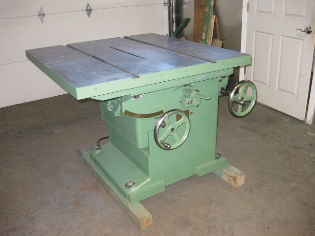
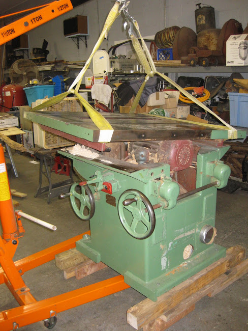
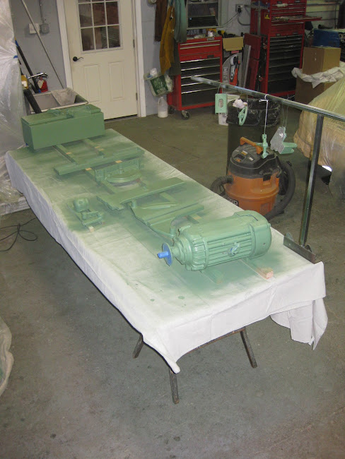
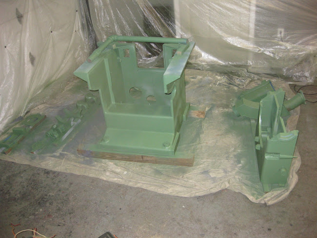
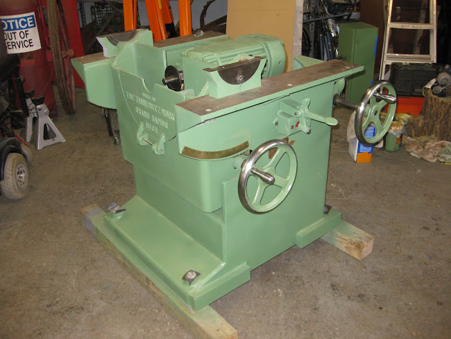
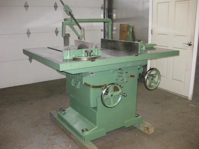
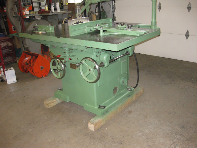
Pete, good observation about the color. I am partial to green: the old Powermatic, Oliver and Northfield. I thought that the color that came with the saw suited it. I had some paint samples from a Northfield table saw I had restored and had a gallon made up. The two turned out to be almost identical, and what you see in the pictures is pretty close to real life.
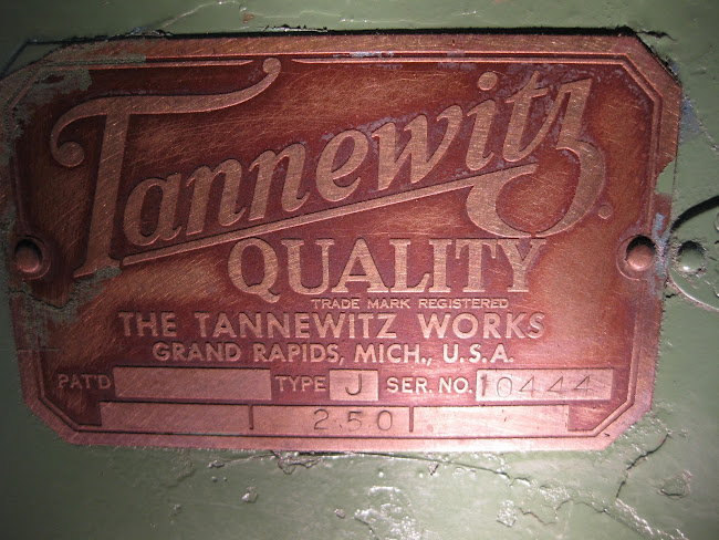
I am on the fence about keeping the saw or selling it. My furniture making business has really taken a hit over the last two years, and I have been supplementing my income by restoring machinery and selling it. That being said, you get up close and personal to a machine when you restore it, and the Tannewitz is probably the best I have come across. So it will be a tough decision for me to make.
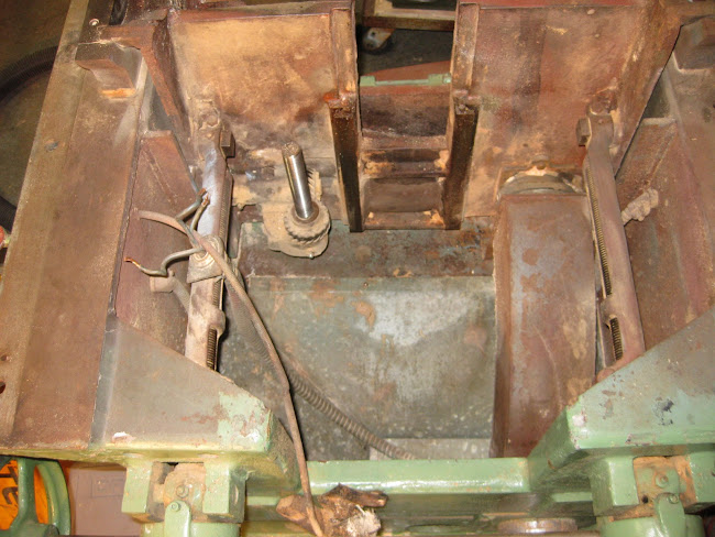
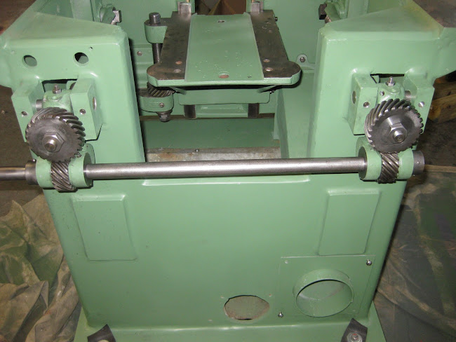
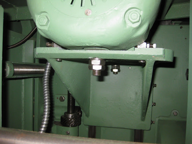
As far as lubrication of the gears, all I have done is put oil in the required ports, and a few drops on the gears. I try to be as sparse with the oil as possible to avoid gumming up everything with the sawdust. However, it sounds like you may be on to something with the graphite. Would you recommend using it over light oil?

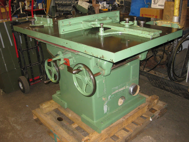
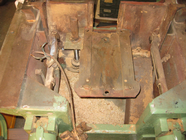
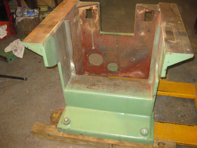
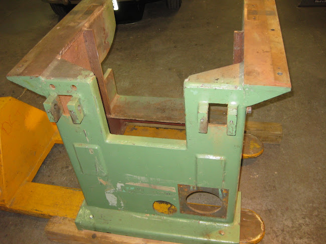
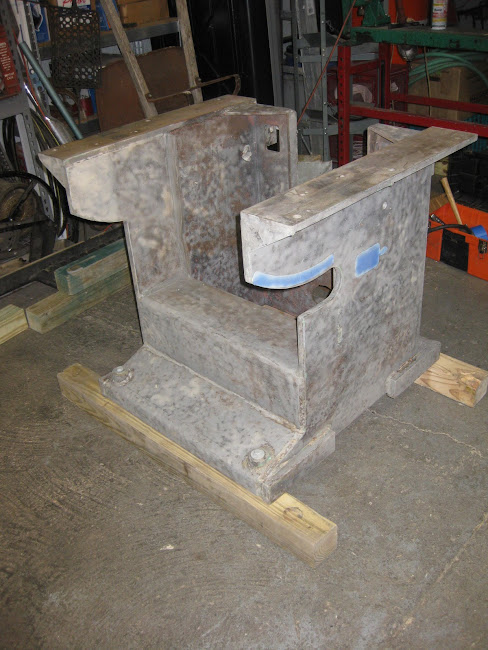
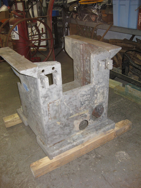
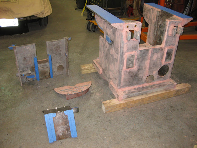
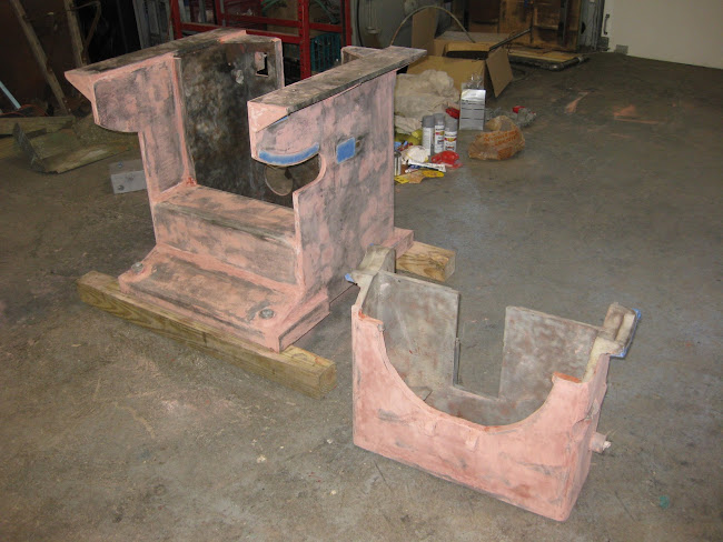
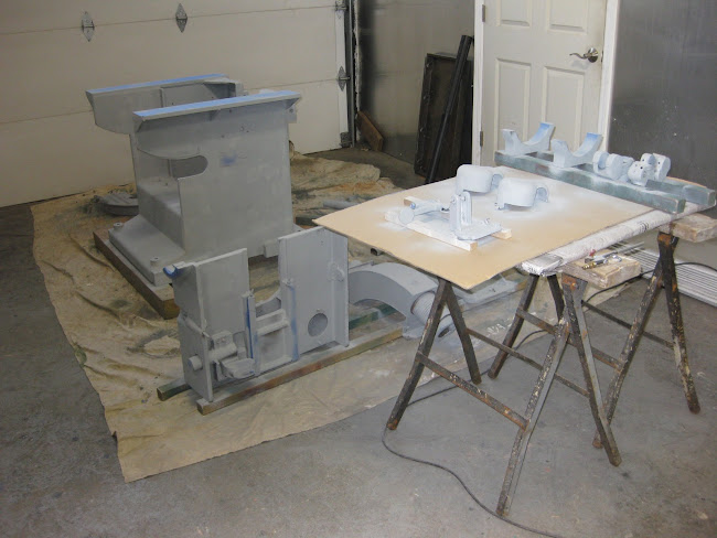
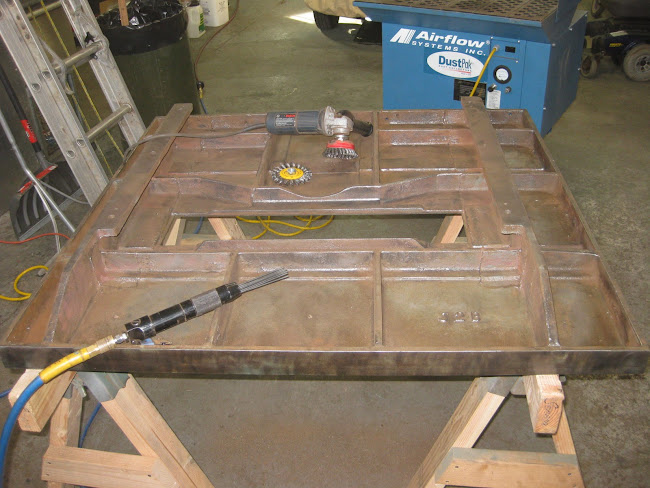
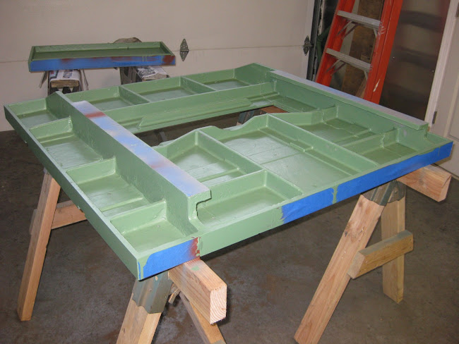
When I got the table on some sturdy saw horses, I realized that I had my work cut out for me to clean the underside. Sixty years of crud, saw dust and old primer were the norm. There was not a square inch that did not need attention. The design of the table with all the ribs for strength and stability is tribute to Tannewitz engineering, but made cleaning all the more time consuming. I decided to use a needle scaler to go after the worst areas, and then a right angle grinder with a cup and circular brush on the less cruddy spots. However, because of the interferences from the ribs, I found it went faster to use the needle scaler on all the surfaces, as it is very good at getting into corners and small areas. After I finished with the needle scaler, I went over the surfaces that I could reach with the wire brushes. All told, cleaning the underside of both tables took about four hours.
Image
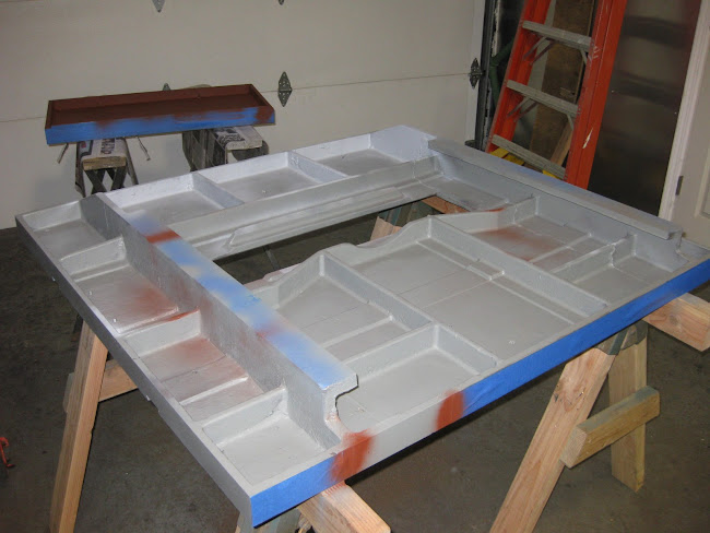
Next came the priming which I did with some leftover rattle cans of primer. I ran out of grey and had to use some rust colored paint I had in another can to finish the work. I applied the top coat using brushes as the aesthetics for the underside is not important, and I also did not want to have to deal with the preparation and cleanup required for spraying.
Image
Image
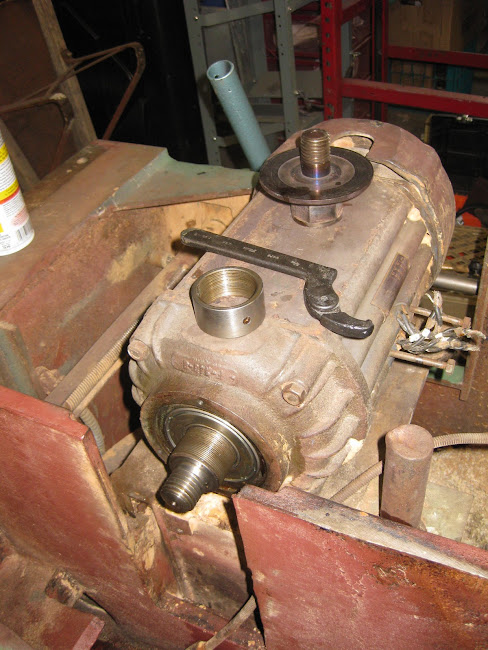
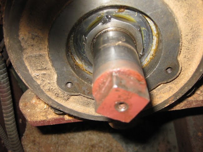
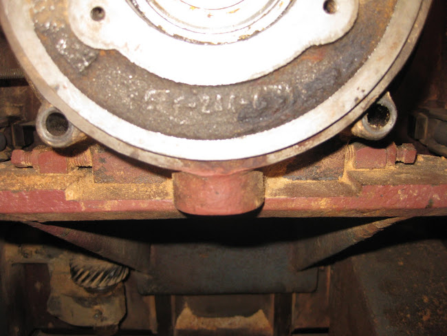
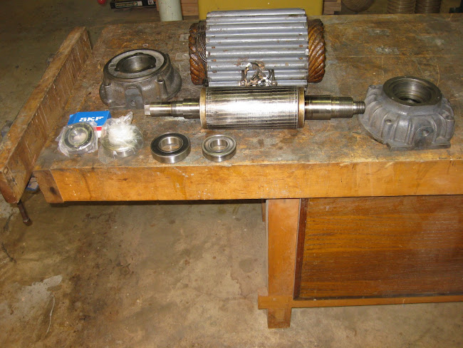
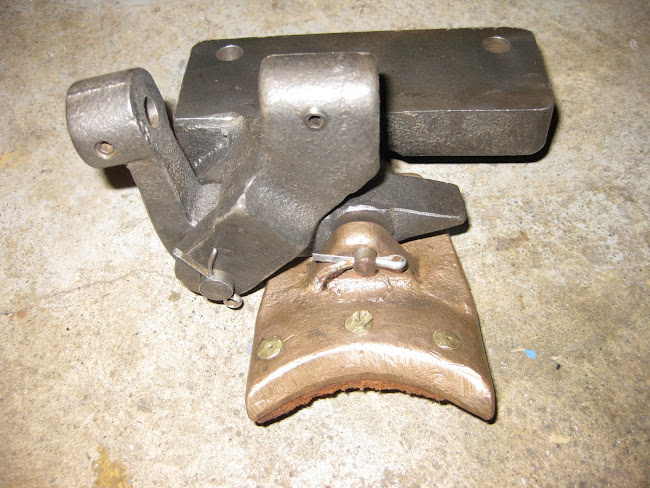
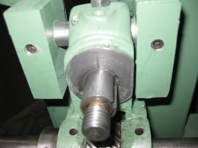
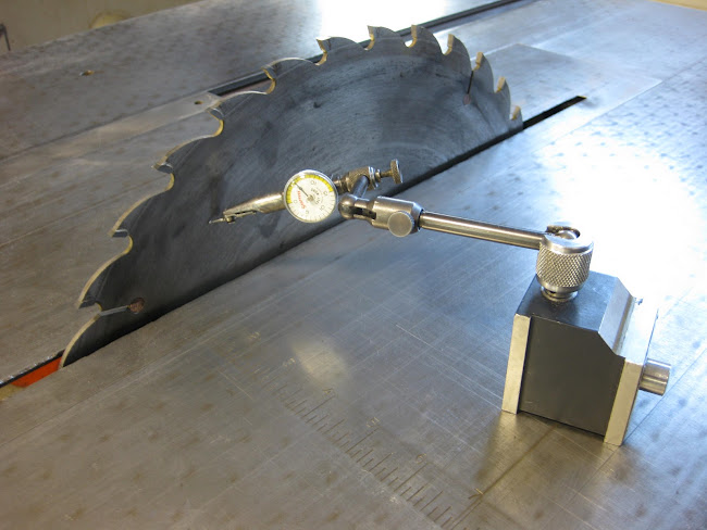
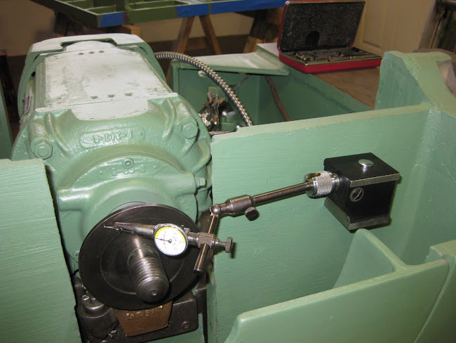
I decided to take a look at the run out on the arbor. I had already checked it out when I bench checked the motor, but wanted the added assurance that nothing had changed. I also used a different dial indicator. I was happy to see that the run out came out to .0005, which was the same as I saw on the bench.
Image
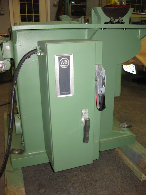
The starter that came with the saw worked, but was very old and tired. The start/stop switch also needed replacing. I kept my eye out on ebay for a starter and switch that were reasonably priced and in good condition. I was able to buy a new Cutler Hammer switch that matched the old switch and fit nicely onto the mounting plate for the brake cable. I also got an Allen Bradley starter and enclosure that were in very good condition. The enclosure was larger than I had expected. However, I like to have a disconnect with the starter, and when you combine this with fuses and a large starter to handle the 7-1/2 hp motor, real estate needed for the enclosure grows. I had to drill and tap holes for the mounting screws and two larger holes for the connectors for the armored cable that went to the motor and start/stop switch. Drilling and tapping those holes was literally a real pain, as I only have hand held electric drill that wanted to tear my hands off when each drill bit broke through the ½” plate. I finally rigged up a wooden cradle that took some of the burden away. I had to use 5 drill bits on each hole to get to the bit required for tapping pipe threads for the connectors. Pete, I would love to have had access to that monster magnetic drill you used on your saw!
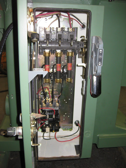
When I got the starter, many of the wires had been cut, and I was not sure how to rewire it. I posted a request for help on OWWM and got a lot of assistance. I was also told that the 120 V coil on the starter was the wrong size. I either needed to replace the 120 V coil with a 240 V coil, or use a step down transformer. An OWWM member was nice enough to send me a transformer gratis. However, the enclosure did not have room to accommodate it, and for aesthetic reasons, I did not want to mount it outside the enclosure. I was able to find a 240 V coil on ebay it and replaced the 120 V coil. I will return the transformer to the OWWM member.
After I had it all wired up, the moment of truth came when I pushed the start button. I was relieved when motor came on and ran quite. However, when I hit the stop button, nothing happened. I pulled the disconnect switch and went to the schematic. I noticed that I had wired the switch wrong, and reversed two wires which solved the problem.
Image
Image
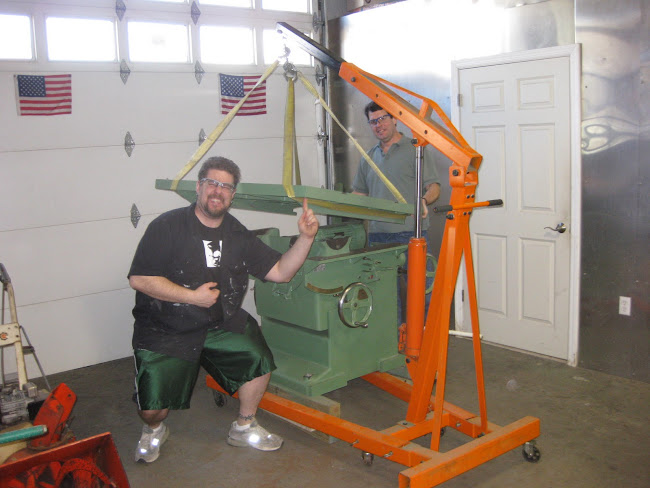
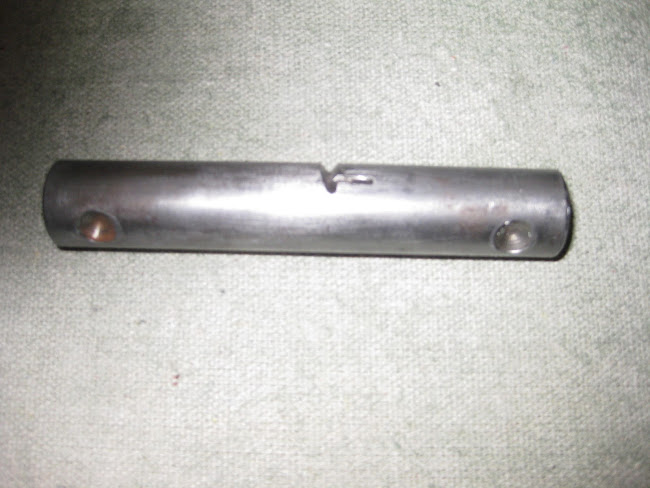
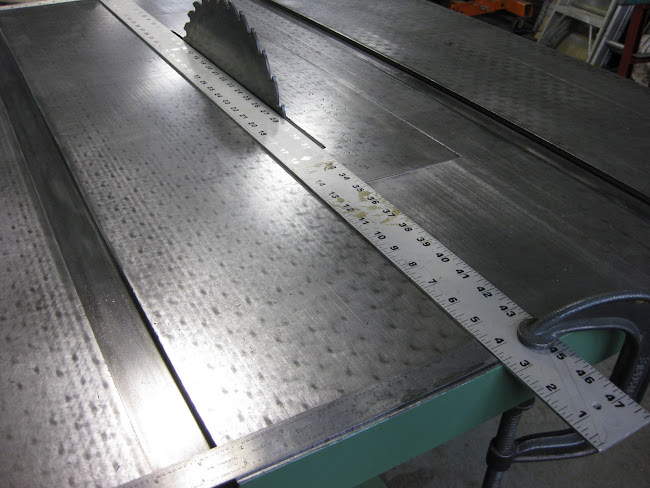
The table went on without a hitch. It helped to have a couple friends to align the table while I maneuvered the shop crane. The six bolts that attach the table to the frame went in with a little help from a rubber mallet to tap the top a fraction of an inch into position. I kept the bolts loose until I could drive the taper pins home, then tightened up the bolts.
Image
Image
Last edited by chathamworkshop on Wed Jan 29, 2014 8:43 pm, edited 3 times in total.
chathamworkshop

Post by chathamworkshop »

Next came positioning the motor and blade to be parallel with the miter slots. The motor is mounted to the carriage with two 5/8” bolts. The base of the motor sits between two adjusting screws that are attached to the carriage. The hole in the carriage that takes the top bolt is a tight fit, but the rear hole in the carriage has some play with the bolt that attaches it to the carriage. Loosening these bolts, allows the motor to pivot left or right when the adjusting screws are turned.
Image
I used a 48” sheet rock square ruler and a machinist’s scale to set the position on the motor. I put a 16” blade on the arbor, tightened the nut, and then placed the 48” ruler against the blade, positioning it in the gullets to avoid the carbide tipped teeth, and clamped it in that position. I measured the distance between the ruler and the miter slot on both ends of the table, and then adjusted the screws until distance to the miter slot on both sides of the table was the same. I then tightened the two mounting bolts for the motor and locking nuts on the two adjusting screws.
Image
I was curious what the run out would be with the 16” saw blade, and was pleased that it turned out to be .0055 using the dial indicator.
Image
I had already painted and reassembled the miter, fence, blade guard, so putting them on the saw went quickly. I also mounted the auxiliary table with its four bolts and two taper pins. I have to say when these came together, the profile of the saw really “popped”, and I realized then why I have always been partial to this particular Tannewitz table saw.
All that remains to be done is to fabricate and mount a dust vent receptacle to the open port on the saw and cut some wood!
Image
Image
Last edited by chathamworkshop on Wed Jan 29, 2014 8:45 pm, edited 3 times in total.
crzypete
Posts: 1691
Joined: Thu Dec 16, 2004 10:45 am
Location: New York State
Contact:

Post by crzypete »

Bill, The saw came out great. I can't believe you are considering selling it. That would make one lucky buyer if you do. I have really enjoyed following along, although the hours of labor seem so trivial when another person is doing them! Love your top lifting crew!

I am noticing that you have an older Ariens Snowblower. just bought one on craigslist, it turned out to be a 1965 unit. I ran it for no more than 10 minutes before it completely gave up the ghost. A new crank arm and governor later is is throwing snow like a champ. I had only paid $75 for the machine, but still, that wasn't what I was bargaining for. We may have to start an older yard equipment section, have you ever heard of a Yazoo master mower? (at least three of our members have them)

Now behind the ariens, I see another tannewitz. Perhaps a 30"? The next machine to be rebuilt?

Pete
chathamworkshop

Post by chathamworkshop »

Pete: Thanks for the encouragement over the last few months and suggesting that I post the progress of the rebuild on Machine Junkie. It was a fun exercise.
I am seriously considering keeping the Tanny. I have to admit that I have fallen in love with it. It also looks like I may have a good commission for a nice piece of furniture, which my business really needs. I am not sure what you are seeing with your business, but down here, the inquiries for custom furniture have really picked up, so I am hoping that will translate into more consistant business down the road.
I have not heard of a Yazoo mower, but I will have to look into them. I am a proponent of Arians blowers. They are well built and reliable.
You have a good eye for machinery! Yes it is a Tanny 30", and yes it is next in line to be rebuilt, but that is another chapter that has yet to be written!
Post Reply