Crzy,
I think you are remembering the recommendation differently than me. My memory is that it is a 3 or 4' 4 x 4 and no hammer. The wood is used as a battering ram to drive the wheel home.
I used this technique on my saw with a chunk of 16/4 I had lying around. It worked very well
Tannewitz 30" PH Band Saw
Moderator: nektai
-
chathamworkshop
The upper and lower brake assemblies were bolted into place with the lower brake being attached with four bolts to the motor housing and the upper brake onto the wheel assembly using one large bolt.
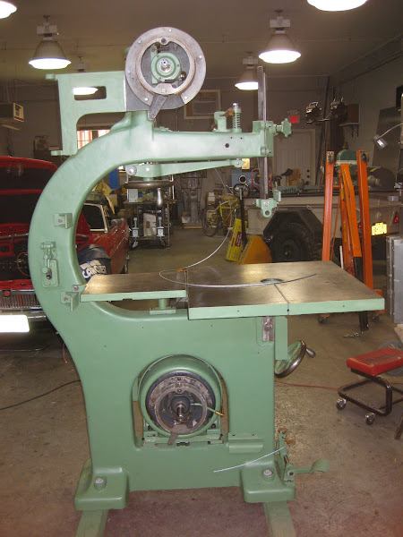
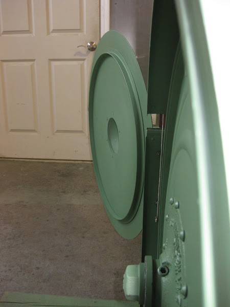
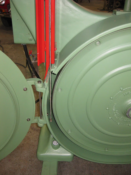
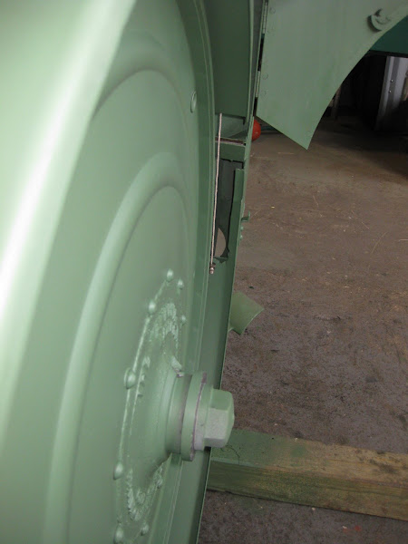
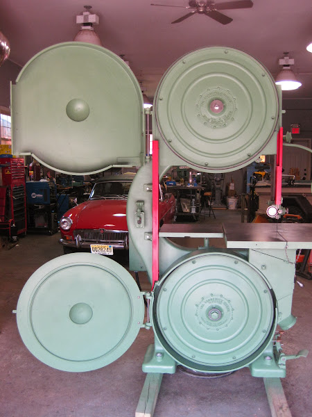
The plate that supports the hinge for the wheel well and door was attached to the upper wheel assembly using six bolts. Next, the lower wheel housing was bolted to the main casting using eight bolts. I decided to also attach the front and rear blade guards. The guards had been repainted fire engine red, which adds some contrast to the overwhelming green in the rest of the saw. The saw itself was now really taking shape, and I could see that the finish line was not far away.
Mounting the wheels was next. The upper wheel went on first. The wheel is quite heavy, and a ladder and a friend were both helpful in getting the wheel into position on the shaft. The key was put on the shaft, and the wheel positioned to line up with the key. Surprisingly, the wheel slid into position pretty easily, requiring only a few taps with a rubber mallet. The two set screws were tightened, and the wheel was firmly in place.
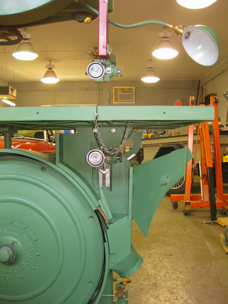
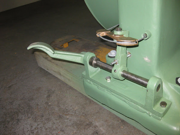
Before installing the lower wheel, the new brake cable was loosely strung in position for the upper brake with plenty of excess cable hanging loose. The other end of the cable was looped through the hole in the lower brake arm and terminated with a cable clamp. When the lower wheel is installed, it covers all access to the lower brake mechanism and cable, so this step had to be completed before the wheel was installed.
Because the lower wheel is close to the ground, it was fairly easy to get it into position on the shaft. Once in position, however, the wheel was pretty stubborn and required a short section of a 2 X 4, a four pound hammer and a lot of pounding to finally drive it into position. You warned me about this possibility, Pete, and you were right. The two set screws were not tightened, as I wanted to check for alignment of the wheels which would come later. The door was also attached to the hinge in the upper wheel backing plate at this time.
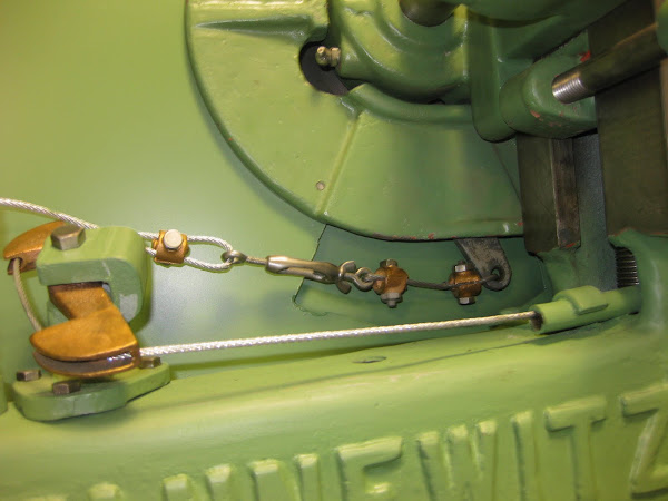
With both wheels in place, the next task was to install the cable mechanism for the upper brake and then adjust the brakes so that they would both work using the foot pedal. The cable transition was mounted on the upper part of the casting arm, and the cable was looped around the transition. The tensioning mechanism and termination for the upper brake cable is simply a turnbuckle and cable clamp. One end of the turnbuckle was attached to the brake arm with a short piece of cable and clamped. The end of the long cable was pulled through the eye of the turnbuckle and enough tension was put on the cable, so that if you pushed on the brake pedal, the brakes would engage. At this point the cable clamp was bolted to the cable. Both the upper and lower wheels were turned alternately by hand, and the brake pedal was depressed. Some tightening was done to the turnbuckle to get both the brakes to stop with reasonable pressure to the pedal.
Next the lower cable was tightened and adjusted. The lower end of the cable is attached to a threaded rod that is attached to the bracket that supports the lower transition for the brakes. The upper end is attached to the stop button through a mechanical arm so that when the brake pedal is pushed, the power is cut off to the saw. The cable was adjusted by tightening the nut on the threaded rod. I had to make sure there was enough movement of the mechanical arm to shut off the saw, but not too much so that over pressure by the arm would damage the switch.
Everything seemed to be functioning properly, but the real test will come when the blade is attached and power is connected to the saw.
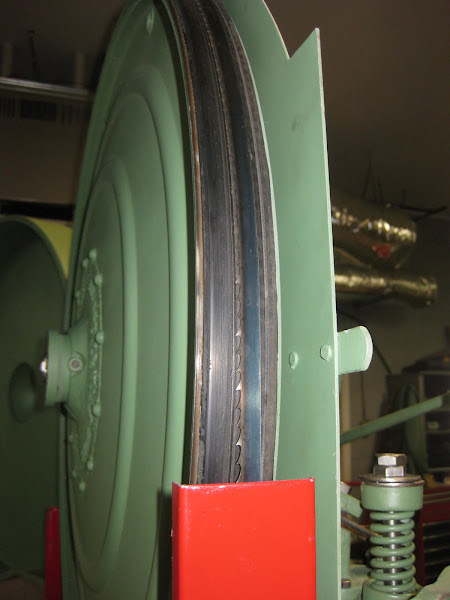
The upper and lower blade guide mounts were installed along with new blade guides, thrust bearings and throat plate. A new ½” blade was also put on at this time. All that remained for start up and testing the band saw was completing the electrical work.
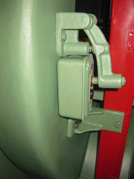
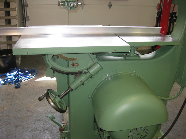
I was not happy with the starter that came with the saw. I purchased a new starter, put it in the original enclosure, and then mounted the enclosure on the saw. Three holes were drilled and tapped to hold the enclosure in place. Next, armored cable was run from the enclosure to the motor along with new wires. New wires were also run from the starter to the start/stop switch, and a new power cord was also installed.
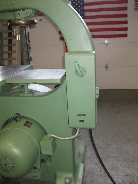
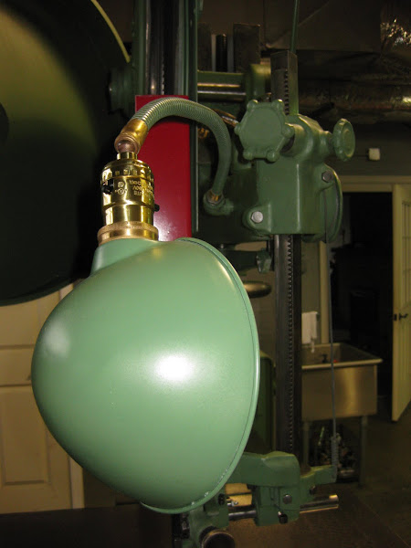
The saw also came with a lamp that had a 110 volt cord that was independent of the saw’s electrical system. I decided to replace the cord and run a new one through cavity in the arm and into the electrical enclosure where it could be connected to power there. This set up is less messy and allows you to turn on the light when the saw is plugged in. To do this, a hole was drilled and tapped into the side of the band saw arm and an elbow with a nipple screwed into that hole. The new lamp cord was pulled from the starter enclosure to the new hole and elbow. The cord was then strung through the neck of the lamp, and the business ends were attached to the terminals in the socket. The lamp neck had a ½” NPT thread that was then screwed into the elbow, and the lamp was good to go. The old lamp shade was broken when I purchased the saw, and was replaced with one that was bought on ebay.

Everything was now in place to set the alignment of the wheels, blade guides and table before the saw was turned on.![Image]()
![Image]()
The plate that supports the hinge for the wheel well and door was attached to the upper wheel assembly using six bolts. Next, the lower wheel housing was bolted to the main casting using eight bolts. I decided to also attach the front and rear blade guards. The guards had been repainted fire engine red, which adds some contrast to the overwhelming green in the rest of the saw. The saw itself was now really taking shape, and I could see that the finish line was not far away.
Mounting the wheels was next. The upper wheel went on first. The wheel is quite heavy, and a ladder and a friend were both helpful in getting the wheel into position on the shaft. The key was put on the shaft, and the wheel positioned to line up with the key. Surprisingly, the wheel slid into position pretty easily, requiring only a few taps with a rubber mallet. The two set screws were tightened, and the wheel was firmly in place.
Before installing the lower wheel, the new brake cable was loosely strung in position for the upper brake with plenty of excess cable hanging loose. The other end of the cable was looped through the hole in the lower brake arm and terminated with a cable clamp. When the lower wheel is installed, it covers all access to the lower brake mechanism and cable, so this step had to be completed before the wheel was installed.
Because the lower wheel is close to the ground, it was fairly easy to get it into position on the shaft. Once in position, however, the wheel was pretty stubborn and required a short section of a 2 X 4, a four pound hammer and a lot of pounding to finally drive it into position. You warned me about this possibility, Pete, and you were right. The two set screws were not tightened, as I wanted to check for alignment of the wheels which would come later. The door was also attached to the hinge in the upper wheel backing plate at this time.
With both wheels in place, the next task was to install the cable mechanism for the upper brake and then adjust the brakes so that they would both work using the foot pedal. The cable transition was mounted on the upper part of the casting arm, and the cable was looped around the transition. The tensioning mechanism and termination for the upper brake cable is simply a turnbuckle and cable clamp. One end of the turnbuckle was attached to the brake arm with a short piece of cable and clamped. The end of the long cable was pulled through the eye of the turnbuckle and enough tension was put on the cable, so that if you pushed on the brake pedal, the brakes would engage. At this point the cable clamp was bolted to the cable. Both the upper and lower wheels were turned alternately by hand, and the brake pedal was depressed. Some tightening was done to the turnbuckle to get both the brakes to stop with reasonable pressure to the pedal.
Next the lower cable was tightened and adjusted. The lower end of the cable is attached to a threaded rod that is attached to the bracket that supports the lower transition for the brakes. The upper end is attached to the stop button through a mechanical arm so that when the brake pedal is pushed, the power is cut off to the saw. The cable was adjusted by tightening the nut on the threaded rod. I had to make sure there was enough movement of the mechanical arm to shut off the saw, but not too much so that over pressure by the arm would damage the switch.
Everything seemed to be functioning properly, but the real test will come when the blade is attached and power is connected to the saw.
The upper and lower blade guide mounts were installed along with new blade guides, thrust bearings and throat plate. A new ½” blade was also put on at this time. All that remained for start up and testing the band saw was completing the electrical work.
I was not happy with the starter that came with the saw. I purchased a new starter, put it in the original enclosure, and then mounted the enclosure on the saw. Three holes were drilled and tapped to hold the enclosure in place. Next, armored cable was run from the enclosure to the motor along with new wires. New wires were also run from the starter to the start/stop switch, and a new power cord was also installed.
The saw also came with a lamp that had a 110 volt cord that was independent of the saw’s electrical system. I decided to replace the cord and run a new one through cavity in the arm and into the electrical enclosure where it could be connected to power there. This set up is less messy and allows you to turn on the light when the saw is plugged in. To do this, a hole was drilled and tapped into the side of the band saw arm and an elbow with a nipple screwed into that hole. The new lamp cord was pulled from the starter enclosure to the new hole and elbow. The cord was then strung through the neck of the lamp, and the business ends were attached to the terminals in the socket. The lamp neck had a ½” NPT thread that was then screwed into the elbow, and the lamp was good to go. The old lamp shade was broken when I purchased the saw, and was replaced with one that was bought on ebay.
Everything was now in place to set the alignment of the wheels, blade guides and table before the saw was turned on.
Last edited by chathamworkshop on Thu Mar 27, 2014 6:20 pm, edited 2 times in total.
Looks great!
Hopefully it is screaming through lumber now.
I pulled out my manual to settle the debate between Nico's thought of pounding the wheel on with the 4x4 and my thought of using a hammer to hit the 4x4 to pound the wheel on. I never found the answer- it wasn;t covered.
However, i did read that the hydraulic brakes was available as an option, so it may have always been a choice for the purchaser rather than a moment when they switched over.
Did you buy the guide parts from tannewitz? how was the pricing? I am in need of calling them to price tires for my 30" last time I called was 12 years ago and they were more expensive than tires for my truck, I don't suspect they went down.
Pete
-
chathamworkshop
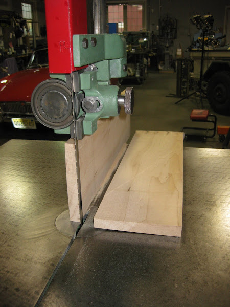
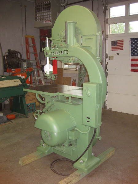
The first order of business was to set the table to be perpendicular to the blade. I used a machinist’s square to align the table and blade. A small adjustment of the table’s angle was made and the table and blade were now perpendicular. I then readjusted stop underneath the table to hold that position and then made a small adjustment to the needle for the degree gauge so it would show zero
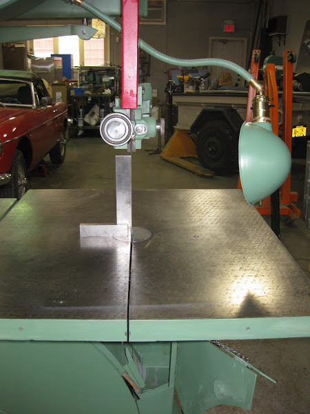
Now that the main table was set, some adjustments were made to the auxiliary table so it would be parallel with the main table. A piece of extruded aluminum was used as a straight edge to establish that both tables were parallel.
The run out on the upper wheel was checked with a dial indicator. I was happy to see that it was .008”.

Next, I used a plumb bob to line up the upper and lower wheels. The bob was taped first to the left and then to the right edges of the upper wheel right in front of the blade. I then checked to see how close each side the wheel lined up with the other. The right side of the lower wheel was short by about 1/8”, and I had to take a 2 X 4 and hammer to the motor mount to move it close to the string. As you may recall, I had left the two adjustment bolts loose for this reason when the motor was originally put into position. The two bolts were then tightened. The alignment was still off by about 1/16” on both sides of the lower wheel, and the motor was moved forward as far as it could go. I then used a wheel puller to move the lower wheel forward enough to align it with the upper wheel. At this point, the two lock screws on the lower wheel were tightened, and the cap nut retightened.
Everything was now positioned correctly and I made one last check to make sure the wheels set screws and the motor mounting bolts were tight.
Before turning on the motor with the blade in position, it is always a good practice to first check the blade tracking manually. It is a bit of a heart stopper if the blade comes off the wheels. Best case is a damaged or ruined blade. Worse case is damage to the band saw or possibly you. I widened the gap in the upper and lower blade guides and moved the thrust bearings away from the back of the blade. This would allow the blade to move back and forth freely while you are trying to center it on the upper wheel. I had already set the upper wheel visually to vertical using the handle for blade tracking. The upper wheel was turned by hand and I made adjustments with the tracking handle until the blade was close to the center of the upper wheel.
The saw was now ready to be turned on, the moment of truth had arrived. However, before hitting the start button, I made sure that the upper and lower doors were all closed and the blade guards were in position. I also positioned myself so that I could have one foot close to the brake pedal when I pushed the switch.
At the click of the magnetic starter, the wheels started accelerating. The blade moved about ¼” forward and then reversed itself before settling into the sweet spot on the wheel. I immediately adjusted the blade tracking handle to bring the blade to the center of the upper wheel. I was happy that the blade stayed on the wheel and I did not have to use the brake when it started up. The acceleration time to full speed was about 7 seconds, as there is quite a bit of inertia to be overcome with the combined weight of the wheels and the armature. The motor was then shut off with the brake pedal and came to a complete stop in about 4 seconds. I was happy with the performance of the brakes.
Next, the blade guides and thrust bearings were repositioned around the blade and I turned the wheels by hand and listened to and watched the movement of the blade through the guides. Some minor adjustments were made. The machine was turned on again. This time I made some very slight changes to the blade tracking handle to move the blade slightly back and forth. I listened and watched for slight changes in sound and vibration until I found what I thought was the optimum spot on the wheel. This position is usually close to, but not always dead center, as the optimum blade position depends on individual blade characteristics, how the wheel was crowned and probably a dozen other variables. The saw was now ready to cut wood.
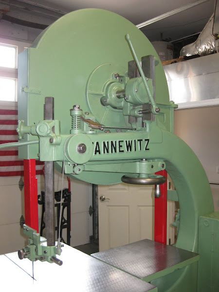
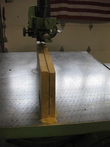
For the saw’s inaugural voyage, I got a piece of 5” thick rock maple from my wood pile, and drew a line down the middle of the wood to follow when cutting. The column for the upper blade guide was raised to accept the piece of wood. The saw was started and I began cutting the wood which went quickly and quietly through the blade. I did not have a bottle of Champaign handy, but the saw was now christened and ready for another 60 years of work!
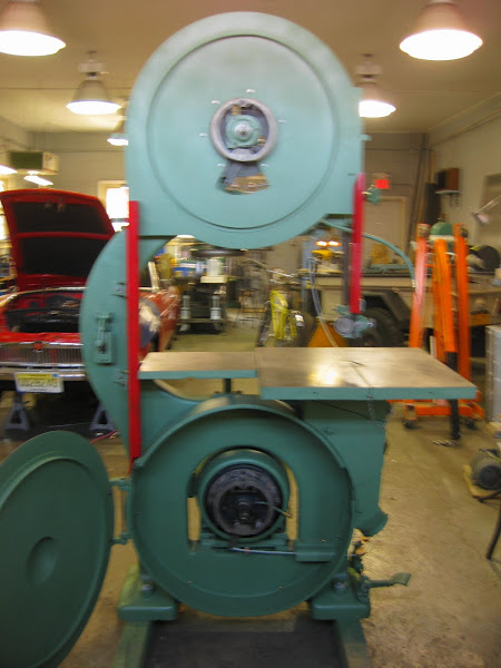
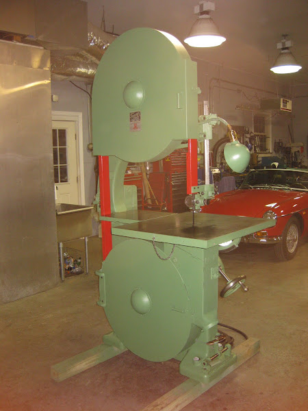
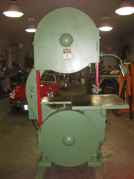
I have added a few profile pictures of the complete saw. You can tell it is itching to go to work.

Now that the main table was set, some adjustments were made to the auxiliary table so it would be parallel with the main table. A piece of extruded aluminum was used as a straight edge to establish that both tables were parallel.
The run out on the upper wheel was checked with a dial indicator. I was happy to see that it was .008”.
Next, I used a plumb bob to line up the upper and lower wheels. The bob was taped first to the left and then to the right edges of the upper wheel right in front of the blade. I then checked to see how close each side the wheel lined up with the other. The right side of the lower wheel was short by about 1/8”, and I had to take a 2 X 4 and hammer to the motor mount to move it close to the string. As you may recall, I had left the two adjustment bolts loose for this reason when the motor was originally put into position. The two bolts were then tightened. The alignment was still off by about 1/16” on both sides of the lower wheel, and the motor was moved forward as far as it could go. I then used a wheel puller to move the lower wheel forward enough to align it with the upper wheel. At this point, the two lock screws on the lower wheel were tightened, and the cap nut retightened.
Everything was now positioned correctly and I made one last check to make sure the wheels set screws and the motor mounting bolts were tight.
Before turning on the motor with the blade in position, it is always a good practice to first check the blade tracking manually. It is a bit of a heart stopper if the blade comes off the wheels. Best case is a damaged or ruined blade. Worse case is damage to the band saw or possibly you. I widened the gap in the upper and lower blade guides and moved the thrust bearings away from the back of the blade. This would allow the blade to move back and forth freely while you are trying to center it on the upper wheel. I had already set the upper wheel visually to vertical using the handle for blade tracking. The upper wheel was turned by hand and I made adjustments with the tracking handle until the blade was close to the center of the upper wheel.
The saw was now ready to be turned on, the moment of truth had arrived. However, before hitting the start button, I made sure that the upper and lower doors were all closed and the blade guards were in position. I also positioned myself so that I could have one foot close to the brake pedal when I pushed the switch.
At the click of the magnetic starter, the wheels started accelerating. The blade moved about ¼” forward and then reversed itself before settling into the sweet spot on the wheel. I immediately adjusted the blade tracking handle to bring the blade to the center of the upper wheel. I was happy that the blade stayed on the wheel and I did not have to use the brake when it started up. The acceleration time to full speed was about 7 seconds, as there is quite a bit of inertia to be overcome with the combined weight of the wheels and the armature. The motor was then shut off with the brake pedal and came to a complete stop in about 4 seconds. I was happy with the performance of the brakes.
Next, the blade guides and thrust bearings were repositioned around the blade and I turned the wheels by hand and listened to and watched the movement of the blade through the guides. Some minor adjustments were made. The machine was turned on again. This time I made some very slight changes to the blade tracking handle to move the blade slightly back and forth. I listened and watched for slight changes in sound and vibration until I found what I thought was the optimum spot on the wheel. This position is usually close to, but not always dead center, as the optimum blade position depends on individual blade characteristics, how the wheel was crowned and probably a dozen other variables. The saw was now ready to cut wood.
For the saw’s inaugural voyage, I got a piece of 5” thick rock maple from my wood pile, and drew a line down the middle of the wood to follow when cutting. The column for the upper blade guide was raised to accept the piece of wood. The saw was started and I began cutting the wood which went quickly and quietly through the blade. I did not have a bottle of Champaign handy, but the saw was now christened and ready for another 60 years of work!
I have added a few profile pictures of the complete saw. You can tell it is itching to go to work.
Last edited by chathamworkshop on Fri Mar 28, 2014 11:44 am, edited 2 times in total.
Reeves variable speed drive
I am posting in a topic way earlier discussed but I have a question about the reeves variable speed drive. I just bought a 36" tannewitz bandsaw off a guy who had no clue what it was and he also had the reeves 7.5 horse motor. I didn't think that the reeves went with it so I didn't buy it. I still could but what is the benefit of it versus a new one like a 10th the size?
great restoration
Bill,
I wanted to ask if you have any thoughts or impressions in hindsight about this machine. I am thinking about getting one, a PH model from 1936 or so, although the expense and restoration effort are both a bit daunting. Even so, I don't know that I would really want the 36" version, even though they seem far more plentiful, and I don't expect that I will have another chance at a nice vintage 30" Tannewitz any time soon if I let this one pass by.
Is there a different 30" saw you would rather own? Has the Tannewitz lived up to your expectations? Are there pros and cons to this saw that you are aware of now that you hadn't thought of when you were first working on it?
Thanks,
Andy