Ruler and Acme Rod Conversion

Discuss the coveted printers saw

Moderator: crzypete

Post Reply
Daninvan
Posts: 50
Joined: Mon Oct 05, 2009 8:55 pm
Location: Vancouver BC

Ruler and Acme Rod Conversion

Post by Daninvan »

I ordered the requisite parts to convert my G4 to inches from McMaster-Carr a couple of years ago. They have been sitting around my shop while I was waiting for the right moment to start the conversion. So I took my piece of 8 TPI Acme rod to a local machine shop to get the necessary turning work done on it. Also took in the round dial and told them to make me a new one with 8 dimples on one face, and 16 on the other. I figured I'd play with it and see which one made the most sense for me. I will pick up those parts on Friday and see how they work.

I was digging through some old threads and came across this posting from 2006 which pointed to a thread on the Practical Machinist that I recall looking at several years ago, but which now seems to have disappeared. Any one know what the new link is?? I think it would be helpful for my new round dial, which will come back from the machine shop unmarked.
crzypete wrote:There is an interesting thread at pratical machinist about creating graduated round dials.

http://www.practicalmachinist.com/ubb/u ... 21848.html

This could inspire hope about a DIY solution for the new hammond rule.

Pete
Thanks,

Dan
crzypete
Posts: 1691
Joined: Thu Dec 16, 2004 10:45 am
Location: New York State
Contact:

Post by crzypete »

Dan, I'm not sure how to find that old post, but I think the gist of it was using a tool on a metal lathe to scratch the line, then indexing. (very basic recount of what was a brilliant and well done post!) Let us know if you find it, I will update the link.

Now onto the conversion- I'm so curious to see! How about some pics?

Pete
Daninvan
Posts: 50
Joined: Mon Oct 05, 2009 8:55 pm
Location: Vancouver BC

Post by Daninvan »

OK I picked up the Acme rod and new ring from the local machine shop, almost 5 hours of labour, boy did that sting!

Here are all the bits and pieces both old and new. I still need to get the ruler trimmed down. You can see the new ring has 16 dimples on it instead of the 12 of the original one. The other side of it has 8 dimples.

Latest problem is that since everything was sitting around the shop for over a year, I seem to have misplaced the Acme nut that I was going to modify to work with the new Acme rod. Progress is again stalled until the nut shows up!

Image
Daninvan
Posts: 50
Joined: Mon Oct 05, 2009 8:55 pm
Location: Vancouver BC

Post by Daninvan »

Well despite turning the shop completely upside down (it is a small shop, one of the reasons I use a Glider rather than a Wadkin PK) the Acme nut I bought from McMaster-Carr to modify for this project ala Crazy Pete's modded nut remains lost. Hope is fading for its recovery. Farewell Acme Nut, we hardly knew ye!

I also thought about making an Acme tap with the leftover piece of Acme rod I have, and tapping a piece of brass (or even lignum or rosewood) to use as a new nut. Not really thrilled by that, basically driving the amount of work required way up.

While staring at the existing bronze nut I was struck by a flash of inspiration: why not grind off the existing threads and use an offcut of the new 3/4-8 rod as a mold to cast some new threads on the existing nut with epoxy or JB Weld etc? Hmmm, I know I have a spare bronze nut so it would seem low risk. Alas, the spare nut is also lost, it has apparently run off with the new nut. So the problem is still under consideration. I really like the modify the existing nut solution though, sounds like way less work to me.

Another related issue is that McMaster-Carr won't ship to Canada, so if I want to cough up for another nut I would have to get it shipped to somewhere in the US and get it forwarded. Not a deal breaker, but a nuisance.

While all this was going on I thought it would be a good time address another problem on my Glider, namely that the faceplate is out of true so the blade wobbles. Still thinking how to resolve that, and I did scrutinize closely Pete's thread on his new arbor. Looks very tempting, but since I would have to pay someone to do it, it could sting the wallet. Anyways, further investigation is needed to narrow down exactly where that problem is originating.

On the good news front, the new Acme rod and index ring fit perfectly in place. I tried the 8 dimple face and the 16 dimple face and I am kind of liking the 16 dimples. With 8 TPI and 16 dimples, that's 1/128th of an inch. With that kind of precision I will be able subcontract my saw to Boeing!

Dan
crzypete
Posts: 1691
Joined: Thu Dec 16, 2004 10:45 am
Location: New York State
Contact:

Post by crzypete »

Dang, 5 hours? Did they actually cut the acme thread rather than using a piece of existing bar? I'm not sure how they used all that time, I am not a machinist and could pull that off way faster. I have sympathy for your wallet.

As to the nut Firstly I believe mcmaster has started shipping to canadian businesses again- you might check that.

Next, I like the concept of soldering a section of nut onto the existing bronze piece. I wish I had saved some of the cut-offs from all the bronze nuts I;ve made through the years. would definitely be an elegant solution if it could be positioned accurately.

You'll want to examine your faceplate carefully. I have encountered damaged ones in the past. Them being out of true is a pretty common occurrence. They are made from pretty soft metal. You can quickly remove jet the faceplate by unscrewing the 5/8" hex on the right side of that whole assembly. It is a drawbar that will release the arbor.

At this moment I am forgetting if I have machined just that piece in the past or if I always attach it to a hammond shaft to have an easier time gripping it.

Pete
Daninvan
Posts: 50
Joined: Mon Oct 05, 2009 8:55 pm
Location: Vancouver BC

Post by Daninvan »

Yeah, it seemed like a lot to me as well. They did make the dimple ring as well, but come on guys! Unfortunately my favourite (cheap) machine shop closed down last year, this was my first and probably last visit to these guys. I have to scout around and find out what other machine shops are in town.

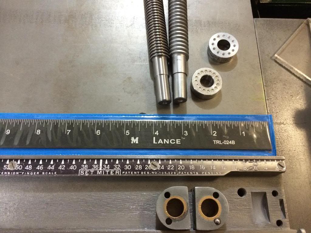
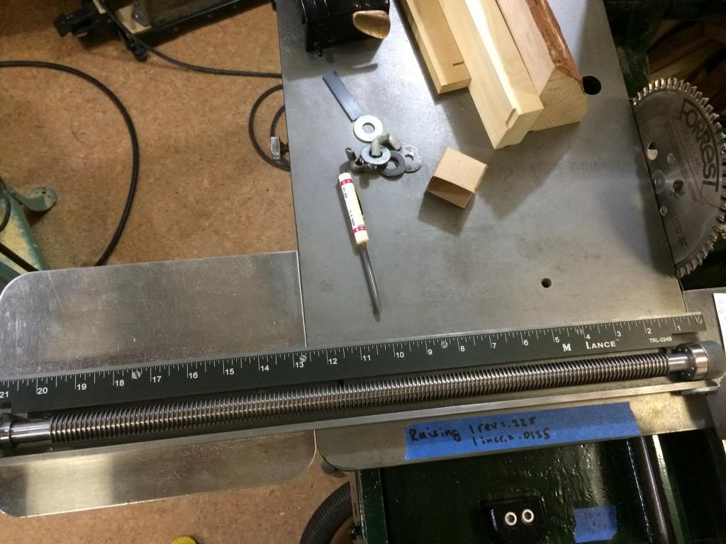
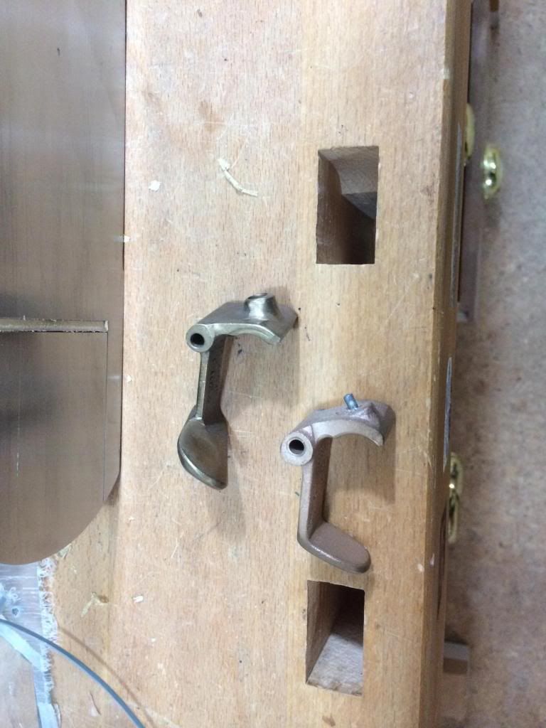
I was able to find my spare nut (actually I found two), I definitely had to widen my search area. It was in a plastic bag hanging from a nail in the garage. Not sure how it got thee, but I'm happy I found it. You can see it is not exactly the same as the original on my machine ( new one is on the right, maybe it's from a 100?). I tested it on my machine though and it fit and worked without issue.

Image

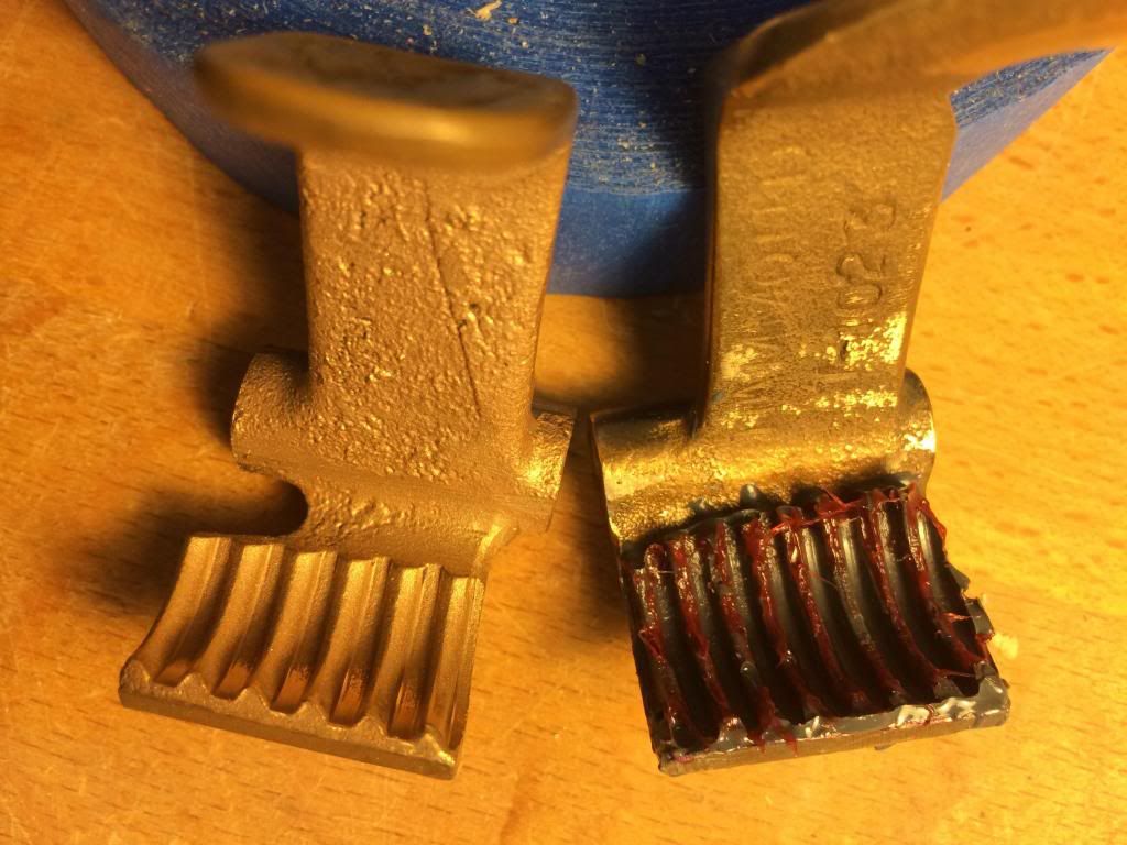
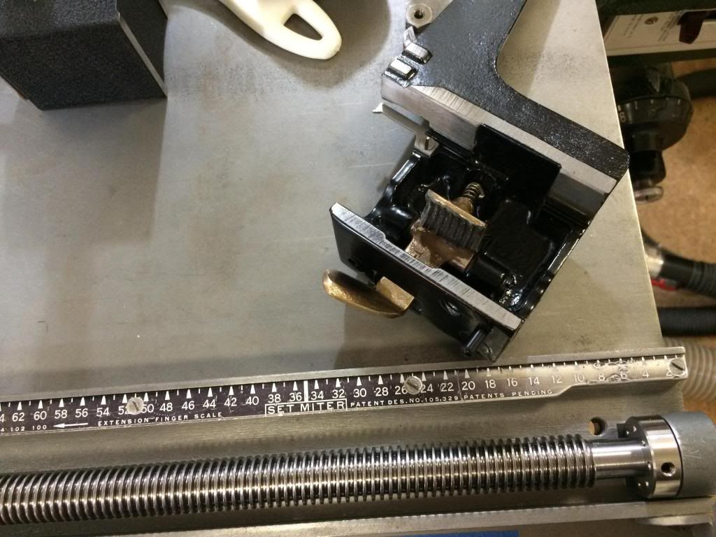
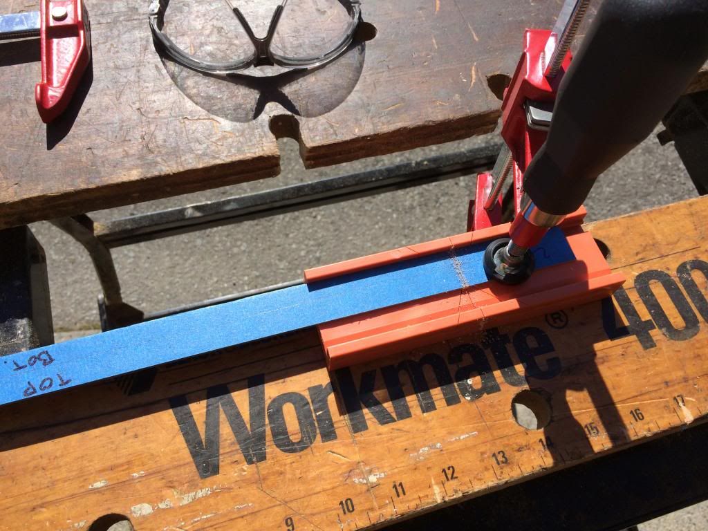
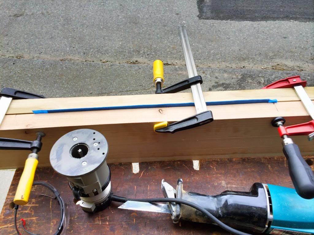
I decided to try to JB Weld new threads on it. There was little to lose, since I had my original still, and one further spare nut. So the first step was to grind off the old threads. I used a piece of the Acme rod with some coarse sandpaper on it to grind them off.

Image

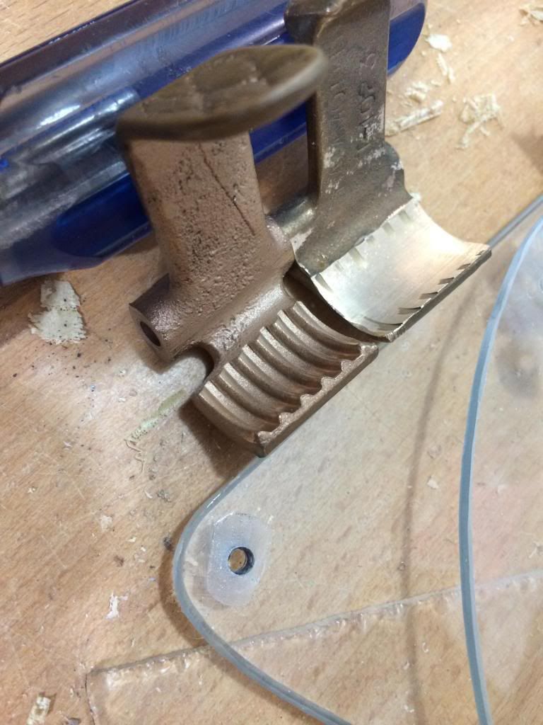
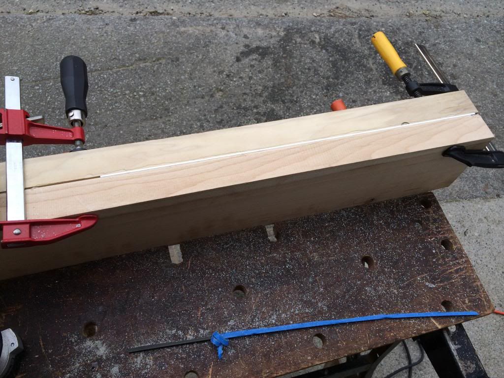
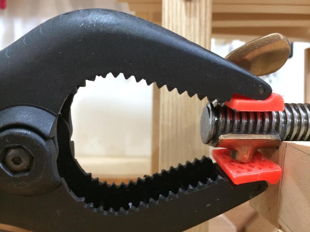
That worked pretty well. I then hit the Acme rod I was going to use as a mold with some wax, then applied the JB Weld, and clamped it overnight.

Image

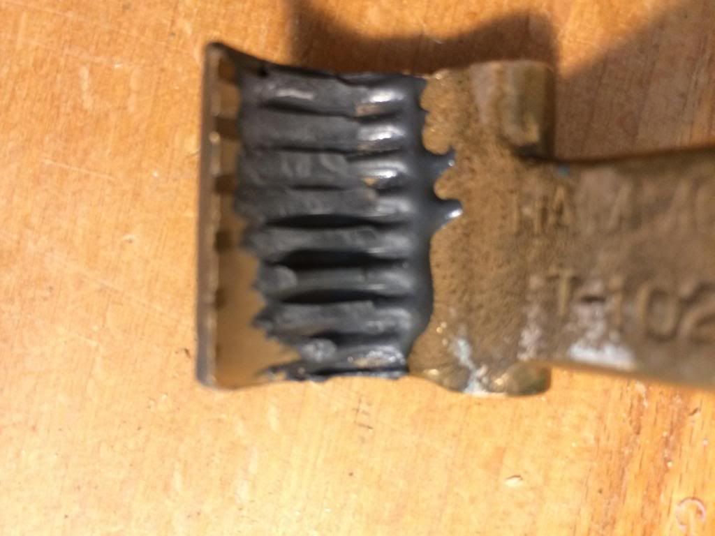
It seems that the wax was not an effective release agent, as most of the JB Weld remained adhered to the rod rather than the nut! So I tried it again, but with WD40 as the release agent, and got the same result. So now I am a little bit stalled again, but will report back when I figure it out.

Image

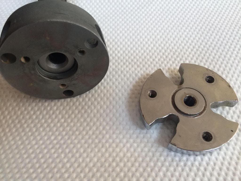
As for the faceplate, mine is quite shiny, makes me think it has been chrome plated or something? I will take it into a machine shop and see what they say.

Image
Daninvan
Posts: 50
Joined: Mon Oct 05, 2009 8:55 pm
Location: Vancouver BC

Post by Daninvan »

Well I tried using lithium grease as a release agent. It worked a whole lot better. Original on the left, new one on the right.
Image

But it also was thick enough that the JB Weld was unable to displace it in some areas, so the new threads are a bit rough and have some voids in them.

So I cleaned up the threads as best I could and reassembled things. I figure that the original nuts are made of bronze so that they don't wear the Acme rod. By using JB Weld I may start to wear out the rod eventually. But I am over 50 years old, so that'll be the next owner's problem!
Image

Anyways, I did a quick test with a dial indicator and a precision block. I zeroed the indicator and moved the new rod 16 indents, or 1/8 of an inch. The block travelled exactly .125 of an inch. I realize that's not at all a complete test, but at least things are trending in the right direction.
Image

Waiting for the faceplate to come back from the shop, once that is reinstalled and aligned, I'll turn my attention to trimming and fitting the ruler.
Daninvan
Posts: 50
Joined: Mon Oct 05, 2009 8:55 pm
Location: Vancouver BC

Post by Daninvan »

OK, got the machined faceplate back and put it on the saw. Definitely cut way down on the blade wobble. There is still a bit, if it bothers me I might order a new blade. This one took a couple big hits when offcuts got jammed between it and the table.

While I was at it I shimmed the arbor to correct a problem with the blade not raising perpendicular to the table. It used to contact the table when it was near the top of its range, now that problem is gone.

There is still a problem with the blade not being perfectly parallel to the table. The back of the blade is about .008" out of line with the front of the blade. I know that on regular table saws people often set the back of the blade to be offset a bit from the front to prevent jamming. I don't think that is needed on a Glider, so I would like to make the blade parallel. Anyone know how to make that adjustment?

Otherwise, it is on to the ruler! I bought two, so if I screw it up I can start over on the other one. I've already scratched one of them. So I concluded they might benefit from a squirt of clearcoat to protect them.

I have not completely figured out how to get the 0" mark of the ruler exactly in line with the kerf of the blade. I read some previous threads on the subject and there were a couple ideas floated, but I am not sure if they were successful.

I'm thinking I might just make the screw holes in the ruler a bit oval, that way I have enough 'wiggle room' to adjust it perfectly. I can see the screws on either end of the ruler might be a problem though, they are so close to the edge.

Dan
crzypete
Posts: 1691
Joined: Thu Dec 16, 2004 10:45 am
Location: New York State
Contact:

Post by crzypete »

Dan,

Thanks for the documenting of this process. i am sure it will be helpful to others down the line who want to achieve this conversion.

Glad to hear the arbor is working better.

As to lining up the ruler, here is how I do it:

First take a six inch rule and get it so the finger is adjusted to cutting exactly six inches. You could do this by actually cutting a piece of wood if you want.

Next scribe that spot into the edge of the fence. (i always use some layout dye (nail polish would suffice in a pinch) and scribe into that.) Perhaps a sharpie would give you enough ink to scribe.

Detach the fence from the saw.

Then I line the precut replacement rule to that mark and clamp it with two very small c clamps.

next I flip it over. You can access the back of those tapped holes and using a wire drill and a cordless drill, I mark each hole.

Then I unclamp the rule and drill and countersink it.

Attach it in place and mark the ends with your scribe to cut it to length.


This has worked very well for me. Keep us posted!

Pete
Daninvan
Posts: 50
Joined: Mon Oct 05, 2009 8:55 pm
Location: Vancouver BC

Post by Daninvan »

Thanks Pete for the explanation on aligning the ruler. I will give it a go. I have decided to order a new blade as well as it is hard to get everything all square if the blade is not flat.

Any tips on how to how to adjust the blade to make it parallel to the sliding table? Mine blade is angled back .008" and it's not obvious to me how to adjust.

Dan
crzypete
Posts: 1691
Joined: Thu Dec 16, 2004 10:45 am
Location: New York State
Contact:

Post by crzypete »

I would guess that the nuts are too tight on the taper pins that hold the whole arbor assembly to the saw. The nuts are really only there to pull those pins out. If they get over tightened, they defeat the purpose of the taper pins which perfectly position that assembly.

I'd loosen all of that and clean it well. Then re-assemble and see how it is aligned. If that fails, you may want to ditch one or both of those taper pins and adjust the blade parallel.

Pete
Daninvan
Posts: 50
Joined: Mon Oct 05, 2009 8:55 pm
Location: Vancouver BC

Post by Daninvan »

Pete,

Good tip, I never would have thought of that backing out those pins other than to remove the arbour.

I purchased a new blade and that has made a world of difference.

Even though the new blade does not seem to be totally parallel to the sliding table, my cuts are perfect. I guess it is really only the leading edge that matters. I will have to remember that when it is the offcut piece I want though!

On the ruler, what I did was use the location of the second hole from the right edge of the ruler to locate the ruler. I screwed a screw into the hole as far as it would go, I theorized this would hold the screw in the centre of the hole. Then I put a 2" wide setup block between it and the finger, then snugged the finger up against it.

Image

I then removed the block and trimmed a piece of wood. I then measured the length of the cut, subtracted 2" to account for the setup block, then subtracted 1/2 of the diameter of the screw's head to give me the exact location of the centre of the screw hole. I got 4.155" Even if it off by several thou, I can still tweak things a bit by moving the blade assembly back and forth as required to make it perfect.

So off to the world's most expensive machine shop later this week to get it done.
Daninvan
Posts: 50
Joined: Mon Oct 05, 2009 8:55 pm
Location: Vancouver BC

Post by Daninvan »

Well the world's most expensive machine stop tried to stick the knife in even deeper this time, so I said forget it and took my ruler home from them and am trying to figure out how to mod it myself. I am trying to avoid cutting it in my basement shop as I don't want the aluminum dust in the house.

I shaved 1/16 or so of the top edge by clamping it between and flush to the top edges of two sections of a 2x4' I had run over the jointer to make perfectly flat. I took that assembly outside, clamped it into my trusty folding workmate bench, and ran a router over it with a 4 flute end mill in it set to a 1/16" depth. Long sleeve shirt, hat, goggles, respirator, gloves, I was mr. safety guy for that cut! The aluminum did not come off in chips, rather it was super fine feathery shavings that went everywhere. Glad I did not do it in the house! Sorry no pics of this operation.

The trickier part will be take the deeper cut off the other side of the ruler. I would like to cut most of the material off first somehow, then do the same trick with the router. Cutting the ends and drilling the holes should be easy, just locating them will be tricky.
crzypete
Posts: 1691
Joined: Thu Dec 16, 2004 10:45 am
Location: New York State
Contact:

Post by crzypete »

Dan, two thoughts:

You could rough it out on a bandsaw with a wood blade quite easily- it's aluminum. then use your router to nab the last 1/16"

Or just make a bunch of steps with the router and your same technique.


The finish line is just around the corner!

Pete
Daninvan
Posts: 50
Joined: Mon Oct 05, 2009 8:55 pm
Location: Vancouver BC

Post by Daninvan »

Thanks Pete!

Cutting the ruler to length was easy to with a fine bladed saw. Just a little bit of touch up with a file afterwards to take the burr off the edge.
Image

I used the second hole as a reference (4.155” from the end) to locate the old ruler on top of the new ruler with some double sided sticky tape.

Then I used a countersink sized for the screws to drill the holes. I used the old ruler as a guide and registered it against a couple blocks of wood as a fence. I drilled from the backside, then flipped the ruler over and did the countersink. Funny that the screw holes are all different distances apart. Kind of like someone just eyeballed the first saw and they never changed it through the whole production run!
Image

Then I mounted the ruler. Yay! It looked good. Unfortunately the finger would not fit, so I had to trim off the back edge of the ruler.
Image

I wound up using a sawzall to rough cut the back side of the ruler, then used the router as before to get the last little bit. I first routed a notch in one of the boards that was just a hair thinner than the new ruler and a hair over 0.5". This allowed the other board to clamp it firmly, and also kept the two long edges parallel. Worked very well.
Image

It works best if you can make the final cut in a single pass without stopping, the result is a smoother edge.
Image

Now one last problem to solve. I cut a sample piece of wood and measured it with the calipers. It’s 3.008” long, but you can see that the indicator on the finger is showing a hair under 3”. I am thinking the easy solution would be just to file the indicator a hair shorter. Another way would be to redrill the screw holes in the new ruler to expand them slightly and move the ruler till it's just right. That would make it so the finger and its indicator are both aligned, and measure the correct cut width. I also looked at the finger, it may be possible to increase the size of the hole in the bottom of it that the indicator screw fits into and thus be able to move the indicator slightly.
Image
crzypete
Posts: 1691
Joined: Thu Dec 16, 2004 10:45 am
Location: New York State
Contact:

Post by crzypete »

Dan, you want the ruler to read correctly without the finger. This way you can by eye use the ruler. I do this all the time and often use a tape measure to hook the end of a long board, then line the 1" mark on the ruler up to an inch shorter than I want on the tape measure. This works remarkably well.

It looks like your ruler is slightly off.

The correct position of the pointer. on the finger scale is perfectly lined up with the finger scale. If you decide to leave the ruler as is, I'd just adjust the length of that pointer.

Welcome to another world of hammond use! You're gonna love it!

Pete
Post Reply